Hardware Installation
Warnings
RISK OF ELECTRIC SHOCK

THE CONTROLLER MUST ONLY BE INSTALLED BY QUALIFIED PROFESSIONALS IN ACCORDANCE WITH APPLICABLE NATIONAL AND LOCAL LAWS AND REGULATIONS.
FOR INDOOR USE ONLY.
DO NOT CONNECT THE MAINS/LINE VOLTAGE TO ANY CONNECTOR ON THE CONTROLLER.
THE CONTROLLER IS INTENDED TO BE INSTALLED INSIDE A CONTROL PANEL OR A BOX AND MUST NOT BE ACCESSIBLE FROM THE OUTSIDE.
DO NOT COVER THE CONTROLLER WITH OTHER MATERIALS DURING USE.
KEEP WATER AND OTHER LIQUIDS AWAY FROM THE CONTROLLER.
Dimension
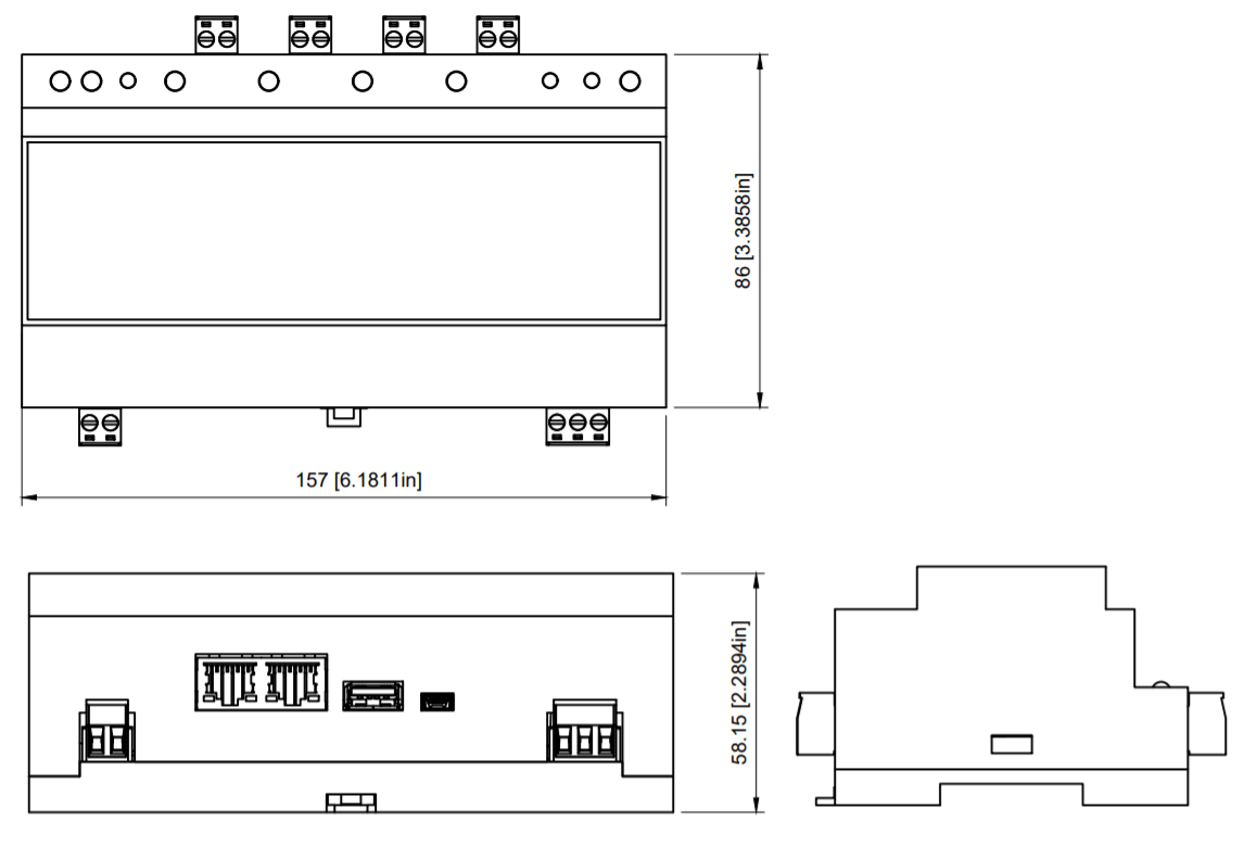
The dimensions are 157 x 86 x 59 mm, 6.181″ x 3.386″ x 2.323″ (L x W x H).

Connectors

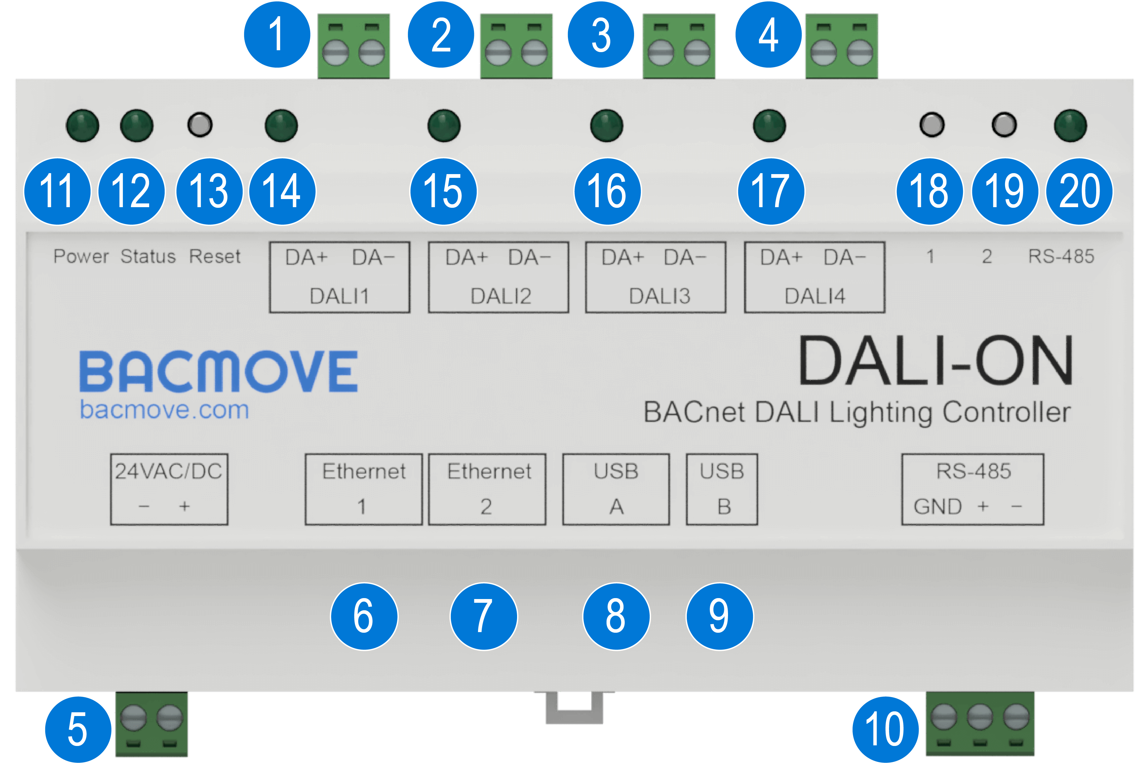
DALI Channel 1 connector
2 position pluggable terminal blocks header of 5.08 mm [0.200"].*DALI Channel 2 connector
2 position pluggable terminal blocks header of 5.08 mm [0.200"].*DALI Channel 3 connector
2 position pluggable terminal blocks header of 5.08 mm [0.200"].*DALI Channel 4 connector
2 position pluggable terminal blocks header of 5.08 mm [0.200"].24 VAC/DC power supply connector
2 position pluggable terminal blocks header of 5.08 mm [0.200"].First Ethernet connector
RJ45 connector. Connect the LAN Ethernet network to this port.Second Ethernet connector
RJ45 connector. Switch port with the first Ethernet connector.N/A
USB device connector
USB 2.0 - Mini-B connector. For the USB console.N/A
Power LED indicator
This LED indicator is on when the DALION is powered.Status LED indicator
This LED indicator blinks to indicate the status of the DALION.Reset IP button
Operate only with electrically insulated tools. Pressing this button for four (4) seconds will reset the IP configurations to the factory default value.DALI Channel 1 LED indicator
Activity LED indicator for the DALI channel 1.*DALI Channel 2 LED indicator Activity LED indicator for the DALI channel 2.
*DALI Channel 3 LED indicator Activity LED indicator for the DALI channel 3.
*DALI Channel 4 LED indicator Activity LED indicator for the DALI channel 4.
Button 1
Pressing this button sends 100% to all lamps on all DALI channels.Button 2
Pressing this button sends 0% to all lamps on all DALI channels.N/A
*The DALI Channel 2, 3 and 4 are only available on the 4 DALI channels model.
Power
The DALION must be powered by a 24 VAC or 24 DC power source.
The supply circuit inside the DALION uses a half-wave rectifier. It can therefore be supplied with the same AC power supply as other devices using a half-wave rectifier. The power supply must be separated from devices using full-wave rectifiers. DC power supply can be shared with other devices.
LEDs Indicators
Power supply
On when the DALION is powered up.
System status
Blink at an interval of 500 milliseconds to indicate that the DALION is operating properly.
DALI channels
Off when there is no DALI power supply. Lit when there is a DALI power supply. Blinks when DALI packets are received.
RS-485
Blinks when transmitting packets.
Ethernet
Green
Indicates the Ethernet link and blink when there is network activity.
Yellow
Indicates the Ethernet speed. LED indicator is on for 100 Mbps, LED indicator is off for 10 Mbps.
Installation
Installation steps:
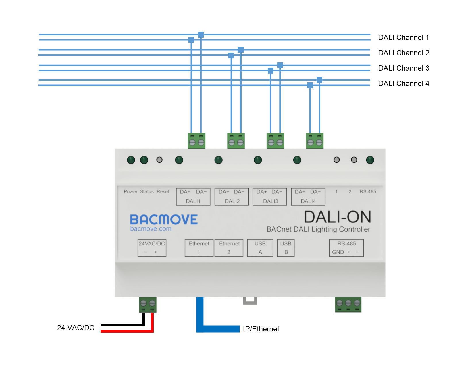
- Install the DALION with the DIN rail fixation.
- Connect the DALION to the DALI channel bus. An external DALI power supply must be present on the bus.
- Connect the DALION to the LAN Ethernet network.
- Connect the DALION to a 24 VAC transformer Class 2 or a 24 VDC power supply.


DALI wiring
The bus wiring must be connected in a star topology, a linear topology or a mixture of the two. Wiring must not be carried out in a ring structure. The two wires that serve as the bus must be located in the same cable or cable conduit. In the cable or cable conduit, the two wires must be side by side to avoid unintentional coupling to other signals.
It is recommended to test the integrity of the DALI wiring. With a multimeter verify that there is no main AC voltage on the DALI wires. DALI devices with no protection will normally be destroyed by the main AC voltage.
