Web User Interface
The web user interface allows modifying system settings as well as performing the DALI devices commissioning.
Responsive Web Interface
The web user interface adapts to all screen sizes.
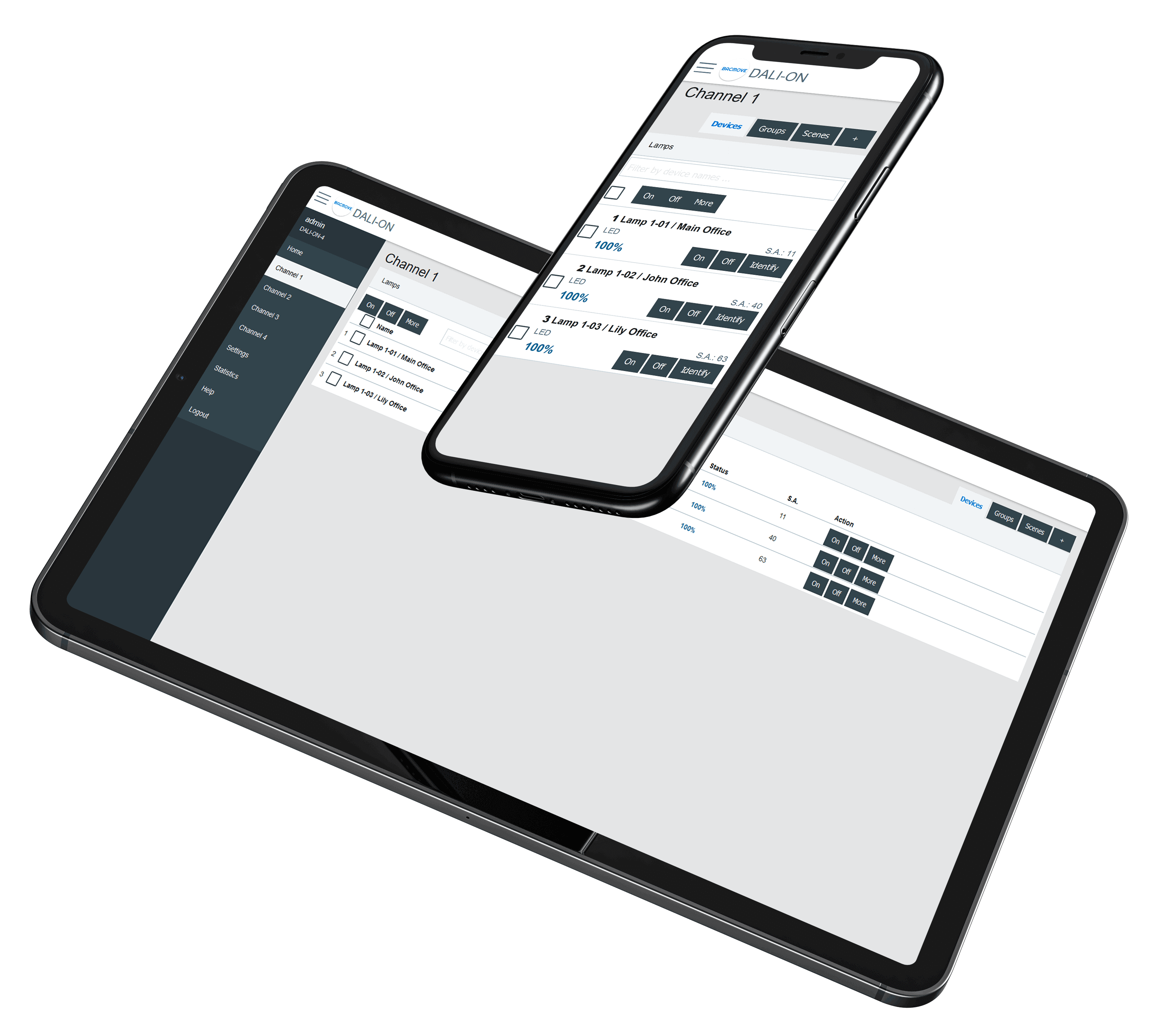
To simplify documentation, the following sections show only screenshots on a desktop computer.
Login
The first page visible when accessing the DALION is the login page.
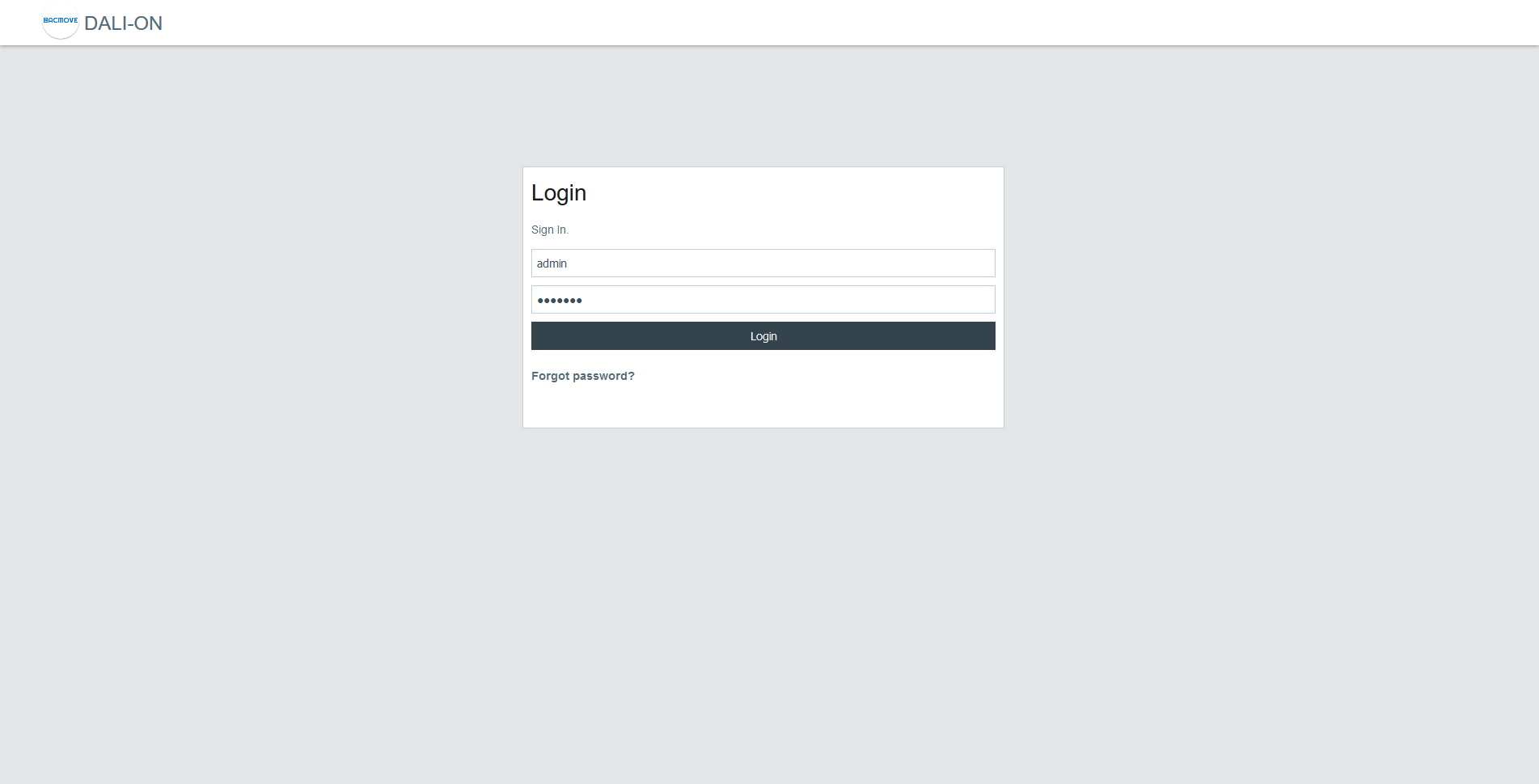
The default login details are as follows.
| Username | Password |
|---|---|
| admin | DALION |
If the password or username is lost, it can be recovered through the USB console.
Home
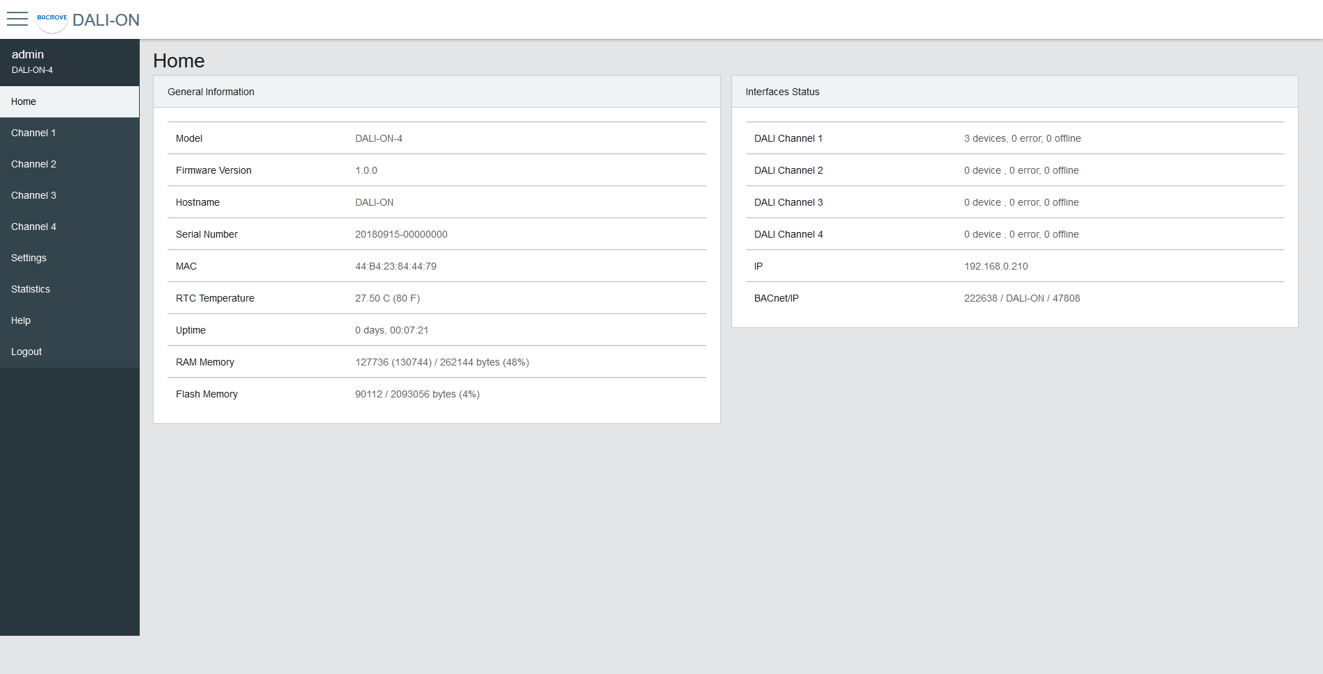
General Information
This section displays some general information about the system.
| Name | Description |
|---|---|
| Model | Model name |
| Firmware Version | Firmware version |
| Build Date | Date of the firmware build |
| Hostname | Hostname of the controller |
| Serial Number | Serial Number |
| MAC | Ethernet MAC address |
| RTC Temperature | Current temperature of the controller |
| Uptime | Time since the last boot of the controller |
| RAM Memory | Usage of the volatile memory |
| Flash Memory | Usage of the non-volatile memory |
DALI Status
This section shows the current status of the DALI interfaces.
| Name | Description |
|---|---|
| Channel | The channel name |
| Status | Green indicates no errors, yellow indicates that at least one device is in error |
| Lamps | The total number of lamps on the channel and the number that are in error |
| Inputs | The total number of inputs on the channel and the number that are in error |
| Utilization | A bar showing the percentage of devices used on the channel |
Rooms Occupancy
Uses the Room Light Control occupancy state to display the number of rooms that are currently occupied.
Schedules Status
Displays the time of the next scheduled event for the current day.
Interfaces Status
This section displays the status of the network interfaces.
| Name | Description |
|---|---|
| IP | Status of the IP network |
| BACnet/IP | Status of the BACnet/IP interface |
Settings
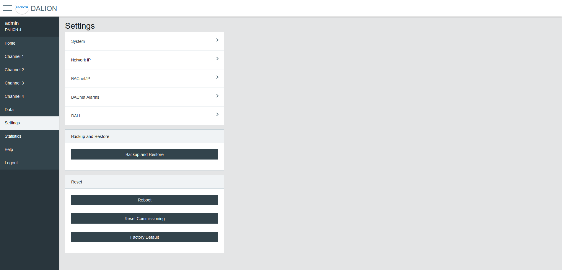
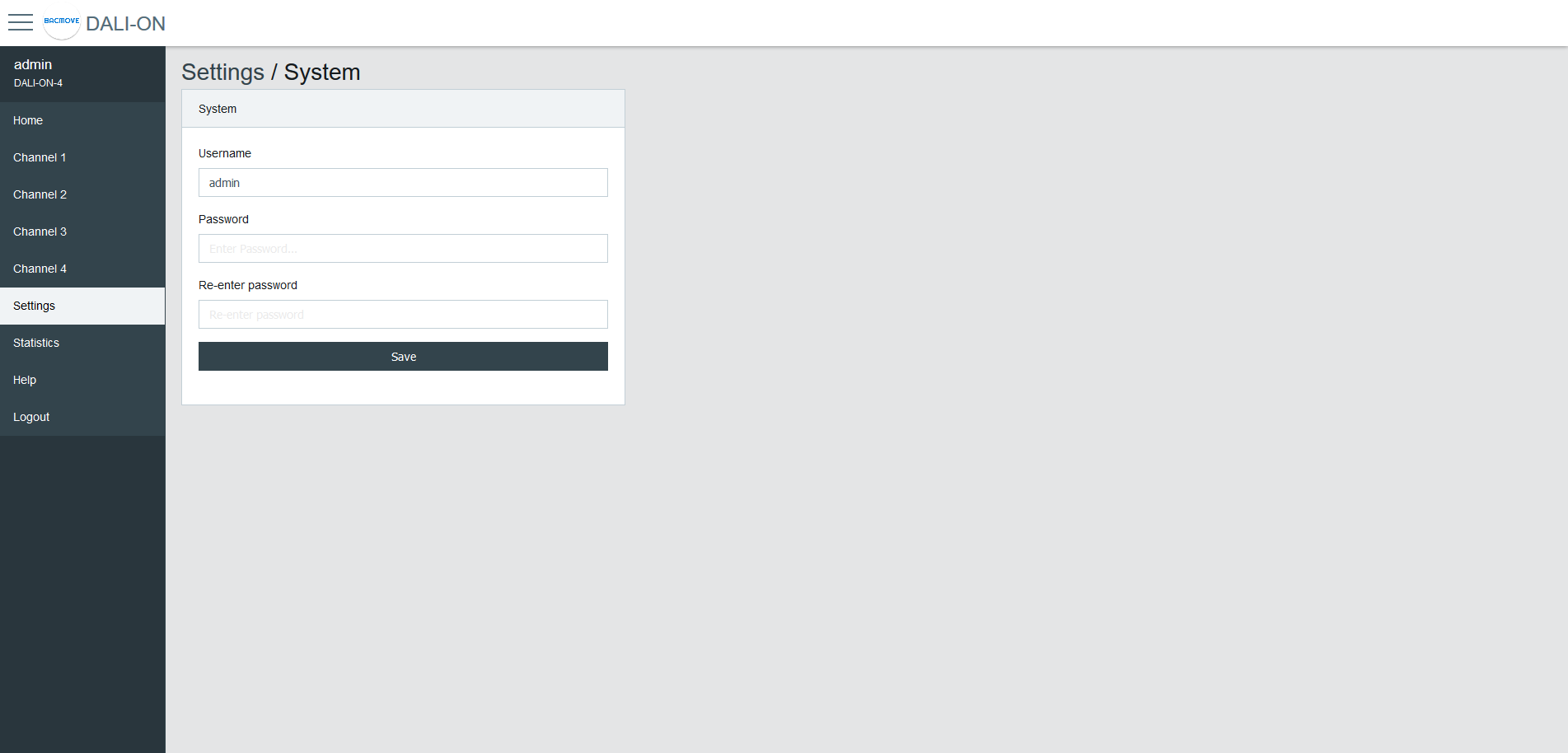
System
The system settings allow changing the username and password.
Date Time
Configuration of the system date and time.
Time Source
Manual uses the configured date and time. BACnet allows setting the date and time with the BACnet TimeSynchronization and UTCTimeSynchronization services.
Local Date
The date to configure in YYYY-MM-DD format. Where YYYY is the year, MM is the month, and DD is the day. MM and DD must be preceded by a 0 if they are less than 10.
Local Time
The time to configure in HH:MM:SS format. Where HH is hours, MM is minutes, and SS is seconds. They must be preceded by a 0 if they are less than 10.
Standard Time Zone Offset
The UTC time offset, for the period of the year when the Daylight Saving Time is not active. The format is [+|-]HH:MM. Where [+|-] indicates the sign of the offset, HH the hours and MM the minutes.
Example
For Eastern Time Zone (EST).
-05:00
DST Time Zone Offset
The UTC time offset, for the period of the year when the Daylight Saving Time is active. The format is [+|-]HH:MM. Where [+|-] indicates the sign of the offset, HH the hours and MM the minutes.
Example
For Eastern Daylight Time (EDT).
-04:00
DST Start - Week
The week of the month when the Daylight Saving Time period starts.
Example
For Eastern Daylight Time (EDT).
2nd
DST Start - Day of Week
The day of the week when the Daylight Saving Time period starts.
Example
For Eastern Daylight Time (EDT).
Sunday
DST Start - Month
The month when the Daylight Saving Time period starts.
Example
For Eastern Daylight Time (EDT).
March
DST End - Week
The week of the month when the Daylight Saving Time period ends.
Example
For Eastern Daylight Time (EDT).
1st
DST End - Day of Week
The day of the week when the Daylight Saving Time period ends.
Example
For Eastern Daylight Time (EDT).
Sunday
DST End - Month
The month when the Daylight Saving Time period ends.
Example
For Eastern Daylight Time (EDT).
November
Hardware UTC Date Time
The currently configured UTC date and time.
Location and language
The language of the web interface is configurable.
Configuration of the local latitude and longitude. The latitude and longitude are used for the calculation of the time of sunrise and sunset for the astronomical time clock schedules.
Language
The supported languages are English and French.
Latitude
The local latitude coordinate that specifies the position of the system in the north or south direction on the surface of the earth. It is measured as an angle, ranging from -90 degrees at the South Pole to 90 degrees at the North Pole, with zero degrees at the Equator.
Longitude
The local longitude coordinate specifies the position of the system in the east or west direction on the surface of the Earth. It is measured as an angle, ranging from minus 180 degrees at the westernmost point to 180 degrees at the easternmost point, with zero degrees at the Prime Meridian.
Sunrise and Sunset of the Year
The table lists all the calculated sunrise and sunset times for the current year, based on the configured latitude and longitude. The first row displays the times for the current day.
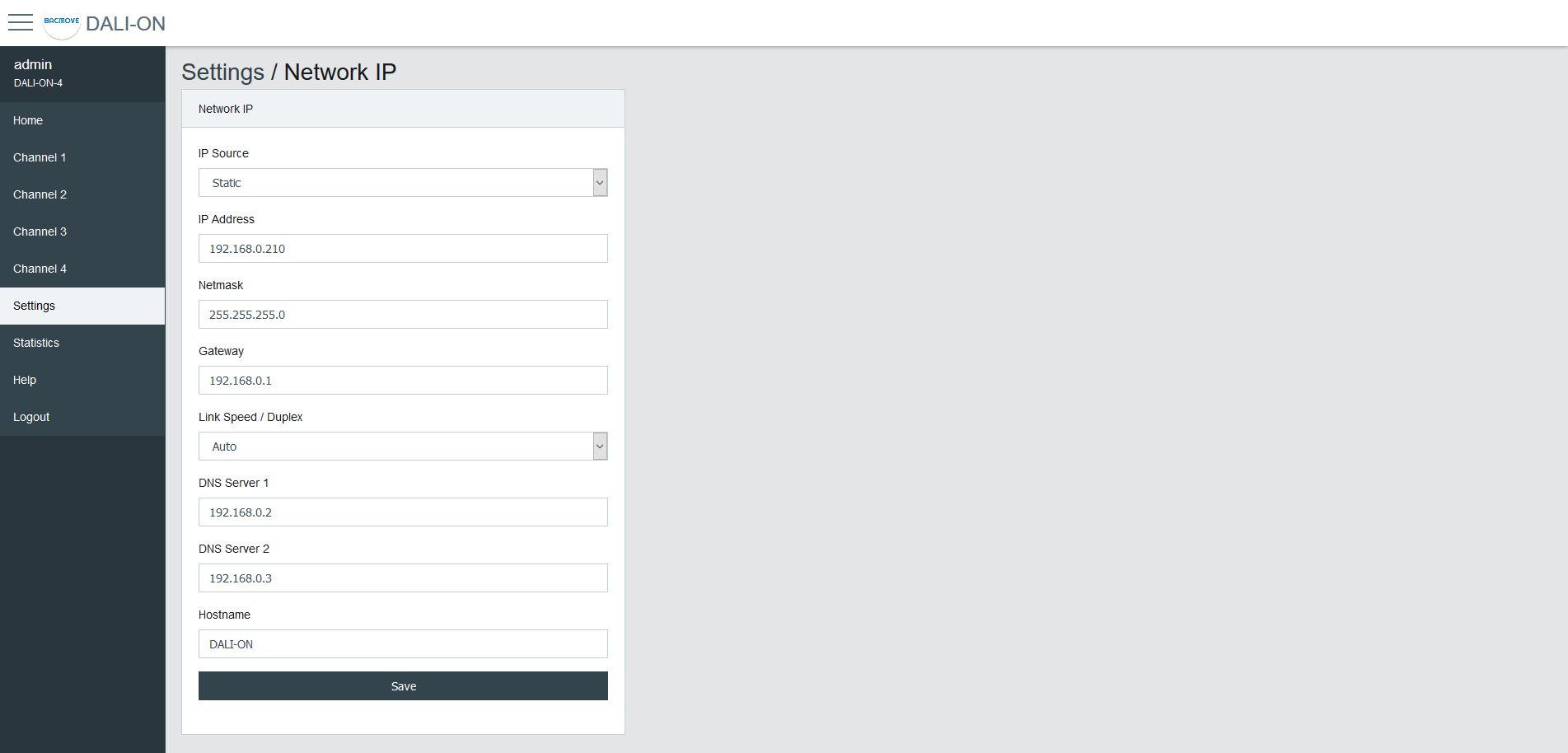
Network IP
Configuration of the IP interface.
By default, the controller uses the IP address 192.168.0.210. To access the controller:
Configure the computer on the same subnetwork.
Open the DALION web interface with a web browser.
| Name | Unit | Limit | Default | Description |
|---|---|---|---|---|
| IP Source | Choice | Static, DHCP | Static | Choice of the IP address source |
| IP Address | IPv4 Address | 192.168.0.210 | Static IP address | |
| Netmask | IPv4 Address | 255.255.255.0 | IP network netmask | |
| Gateway | IPv4 Address | 192.168.0.1 | IP address of the default gateway | |
| Link Speed / Duplex | Choice | Auto, 100F (100 Mbps Full Duplex), 100H (100 Mbps Half Duplex), 10F (10 Mbps Full Duplex), 10H (10 Mbps Half Duplex) | Auto | Ethernet link speed |
| DNS Server 1 | IPv4 Address | 192.168.0.2 | IP address of the first DNS server | |
| DNS Server 2 | IPv4 Address | 192.168.0.3 | IP address of the second DNS server | |
| Hostname | String | 32 characters | DALION | Network hostname |
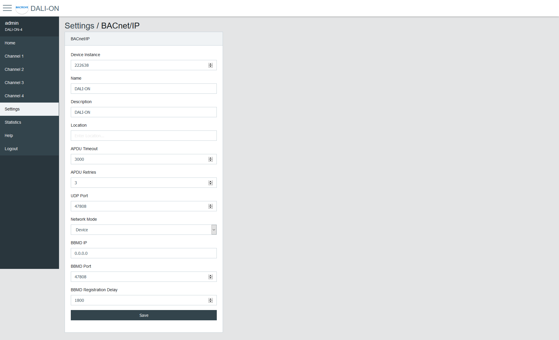
BACnet/IP
Configuration of the BACnet/IP network interface.
| Name | Unit | Limit | Default | Description |
|---|---|---|---|---|
| Device Instance | Number | 0-4194302 | 222638 | BACnet device object instance number |
| Device Name | String | 32 characters | DALION | BACnet device object name |
| Device Description | String | 32 characters | DALION | BACnet device object description |
| Device Location | String | 32 characters | BACnet device object location | |
| APDU Timeout | Number | 0-65535 | 3000 | BACnet APDU timeout |
| APDU Retry Count | Number | 0-65535 | 3 | BACnet APDU Retry Count |
| UDP Port | Number | 0-65535 | 47808 | BACnet/IP UDP Port |
| Network Mode | Choice | Device / Foreign Device | Device | Enable or disable foreign device mode |
| BBMD IP | IPv4 Address | IP address of the BBMD server | ||
| BBMD Port | Number | 0-65535 | 47808 | Port of the BBMD server |
| BBMD Registration Delay | Seconds | 0-65535 | 300 | BBMD Registration Delay |
| Unsubscribed COV Notification - Binary Input | Choice | Enabled / Disabled | Disabled | Enable or disable the sending of unsubscribed COV Notification for the Binary Input objects |
| Unsubscribed COV Notification - Analog Input | Choice | Enabled / Disabled | Disabled | Enable or disable the sending of unsubscribed COV Notification for the Analog Input objects |
| Unsubscribed COV Notification - Multi-state Input | Choice | Enabled / Disabled | Disabled | Enable or disable the sending of unsubscribed COV Notification for the Multi-state Input objects |
| Binary Input - Buttons | Choice | Only Commissioned / All / None | Only Commissioned | Only Commissioned: Only the commissioned input device objects are visible, All: All possible input device objects are visible, None: None of the input device objects are visible. |
DALI
Configuration of the DALI channels.
Mode
- Normal: The controller is operating normally.
- Disable: The controller is not authorized to communicate on the DALI channel. When the mode is Disable, gray bands appear in the background of the associated DALI channel pages.
Lamp Command Repeat Count
The commands that affect the light intensity of the lamps can be repeated.
Assign Match Short Address with Index
If enabled when assigning a lamp or input, its short address will automatically be modified to match the assignment index number.
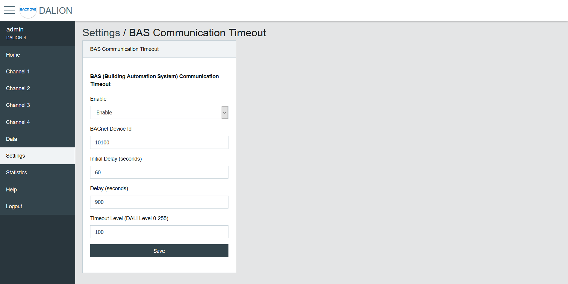
BAS Communication Timeout
In the event of loss of communication between the DALION and another BACnet device such as a BAS (Building Automation System), the DALI channels and groups can reach a specified light brightness. The commands executed when the timeout is reached are configured through the pages of each group and channels.
| Name | Unit | Limit | Default | Description |
|---|---|---|---|---|
| Enable | Choice | Enable / Disable | Disable | Enable or disable the communication timeout |
| BACnet Device Id | Number | 0-4194302 | 0 | BACnet device id of the other device (BAS) |
| Initial Delay | Number | 0-4194302 | 0 | Initial Delay in seconds. Used to let time to the other device (BAS) to boot-up |
| Delay | Number | 0-65535 | 0 | Delay in seconds before the communication timeout |
| Timeout Level | Number | 0-255 | 0 | Default light intensity level |
Network IP - Remote Capture
The Remote Capture feature allows BACnet/IP traffic received and transmitted to be mirrored and sent to a specified remote IP address.
This enables the analysis and troubleshooting of BACnet communication using external tools such as Wireshark.
It is useful for diagnosing network problems, verifying device behavior, or recording protocol exchanges without requiring a network TAP (Test Access Point) or switch with port mirroring.
Sending packets to the remote host begins approximately 2 minutes after boot-up.
| Name | Unit | Limit | Default | Description |
|---|---|---|---|---|
| Enable | Choice | Enable / Disable | Disable | Enable or disable the forwarding of BACnet/IP packets to the remote capture host |
| Remote IP Address | IPv4 Address | The IPv4 address of the computer running the packet capture software. This host must be reachable | ||
| Remote Port | Number | 0-65535 | 47808 | The UDP port on the remote host where packets are sent. Default 47808 corresponds to the standard BACnet/IP port but can be set to another value if needed by the capture software |
⚠ Remote Capture is intended for diagnostics and testing. It should normally remain disabled during standard operation to avoid unnecessary traffic.
⚠ Forwarding packets increase memory and network usage. On busy networks, enabling this feature continuously is not recommended.
⚠ Ensure that the remote host is running a packet capture tool (e.g., Wireshark) configured to listen on the defined port.
Syslog Client
The Syslog Client allows forwarding system and application messages to a remote Syslog server for monitoring, diagnostics, and logging purposes.
| Name | Unit | Limit | Default | Description |
|---|---|---|---|---|
| Enable | Choice | Enable / Disable | Disable | Activate or deactivate the Syslog client |
| Syslog Server IP Address | IPv4 Address | Specify the IP address of the remote Syslog server | ||
| Syslog Server Port | Number | 0-65535 | 514 | Specify the UDP port of the remote Syslog server. Default is usually 514 |
The Sources define which internal modules or events generate Syslog messages. Each source can be enabled or disabled depending on the required logging.
⚠ Syslog Client is intended for diagnostics and testing. It should normally remain disabled during standard operation to avoid unnecessary traffic.
⚠ Syslog messages increases memory and network usage. Enabling this feature continuously is not recommended.
⚠ Enabling the Syslog Client may generate a large number of network messages depending on the selected sources. This can increase network traffic and load on the Syslog server. It is recommended to enable only the sources required for diagnostics.
Backup / Restore
Please use the Tool software to backup and restore the configurations.
Reboot
This page allows the system to restart. Some configurations, such as network settings, require a system reboot.
Reset Commissioning
This page removes the commissioning data by deleting all lamps, groups, and scenes from the configuration. The commissioning data can be reset for each channel individually.
Factory Default
This page allows resetting all settings and commissioning data to their factory default values.
DALI Commissioning
Lamps
This page displays the list of commissioned lamps. The list provides a descriptive Name of each lamp as well as other information like Actual Level, Type and short address S.A..
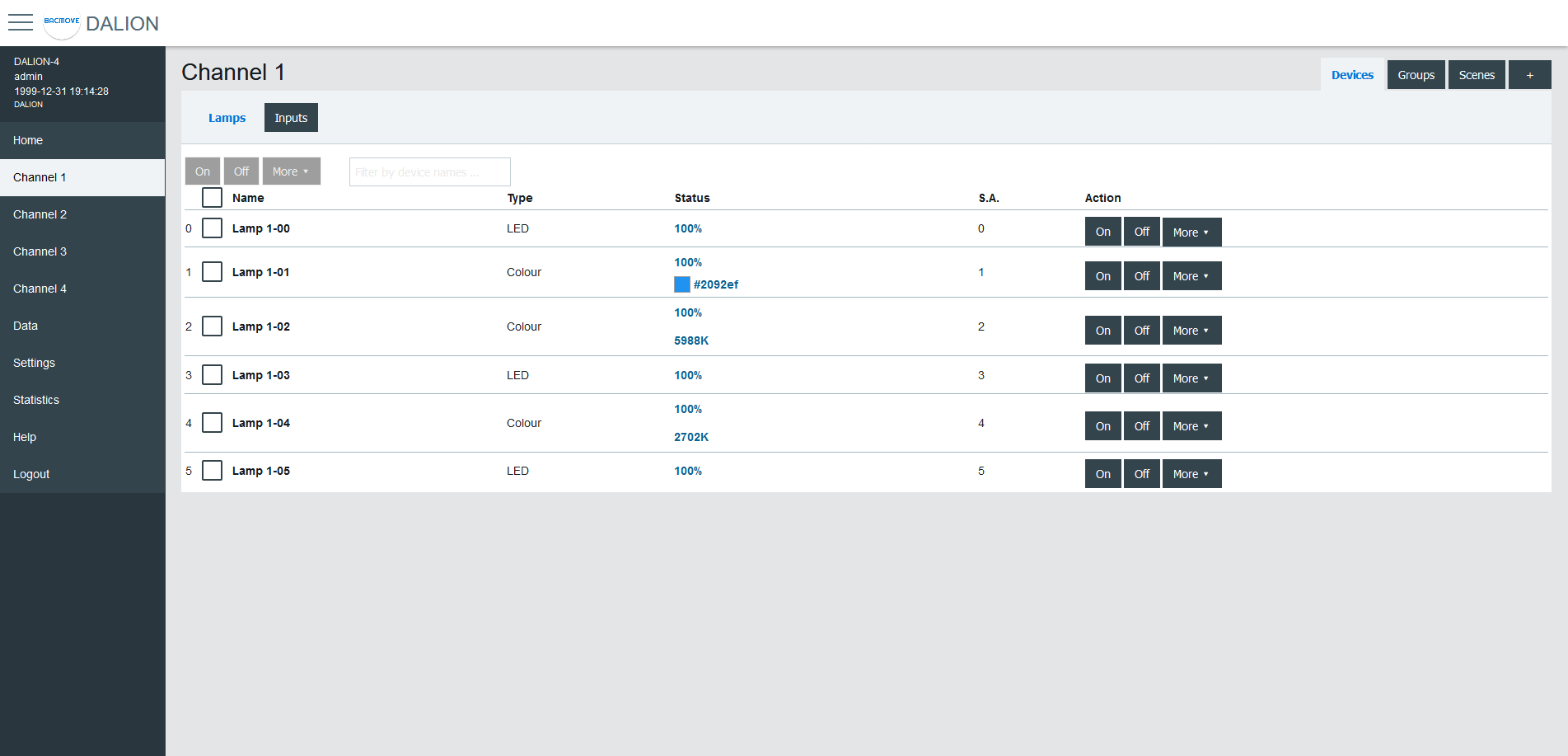
Lamps can be turned On, Off or we can Set Level in a percentage of its light intensity. Notify helps to identify a lamp by dimming it in a loop between its minimum and maximum light intensity. Unassign removes the lamp from the list of lamps while Delete also removes the lamp from the list, but also resets its DALI parameters to the default values.
For the lamps with colour control, available with DALI Type 8 (DT8) lamps, the current colour can be modified with Set Colour.
By clicking on a lamp row, the Lamp Parameters page opens.
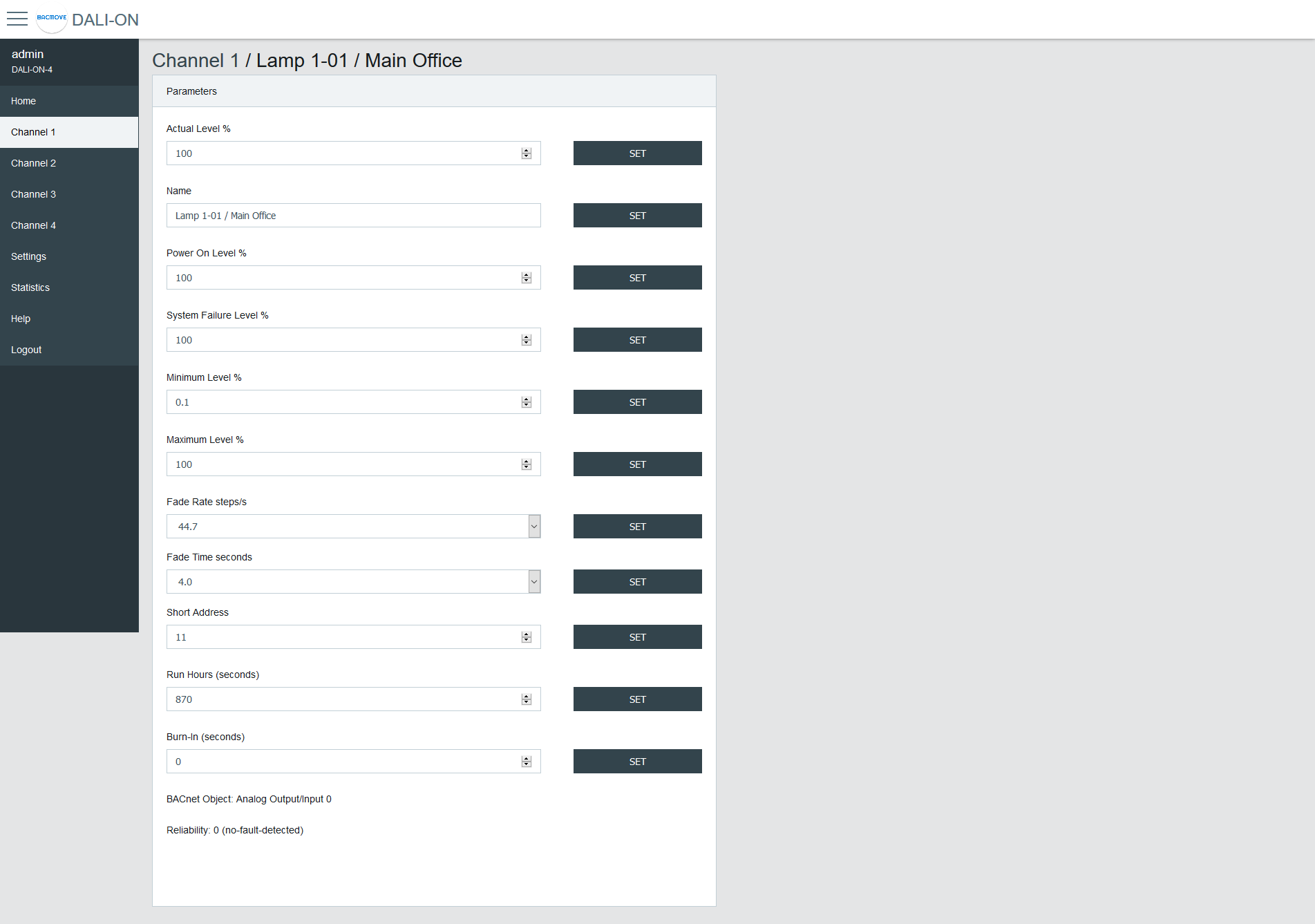
Lamp Parameters
This page allows the configuration of lamp parameters.
| Name | Unit | Minimum | Maximum | Default | Description |
|---|---|---|---|---|---|
| Actual Level | Percent | 0% | 100% | Actual light intensity | |
| Name | String | 32 characters | Name of the lamp | ||
| Power On Level | Percent | 0% | 100% | 100% | Level of intensity after a power on |
| System Failure Level | Percent | 0% | 100% | 100% | Level of intensity when system failure |
| Minimum Level | Percent | 0.1% | 100% | 100% | Minimum level of intensity |
| Maximum level | Percent | 0.1% | 100% | 100% | Maximum level of intensity |
| Fade Rate | Choice | 2.8 | 358 | 44.7 | Fade rate in steps per second |
| Fade Time | Choice | No Fade | 90.5 | No Fade | Fade time in seconds |
| Short Address | Number | 0 | 63 | The short address | |
| Run Hours | Number | 0 | 65535 | 0 | Number of seconds where the lamp was on |
| Nominal Power | Number | 0 | 4294967 | 0 | Nominal power |
| Burn-In | Number | 0 | 65535 | 0 | Number of seconds remaining to the burn-in |
| Dimming Curve | Choice | Logarithmic | Linear | Logarithmic | Dimming curve |
| Energy Usage Accumulated | Number | 0 | 42949672 | 0 | Energy usage accumulated |
| BACnet Object | The BACnet object associated with the lamp | ||||
| Reliability | Reliability of the lamp |
Emergency Parameters
For the lamps of the type "Self-contained emergency lighting (device type 1)", other parameters are available. When emergency parameters are available, a tab Emergency is added.
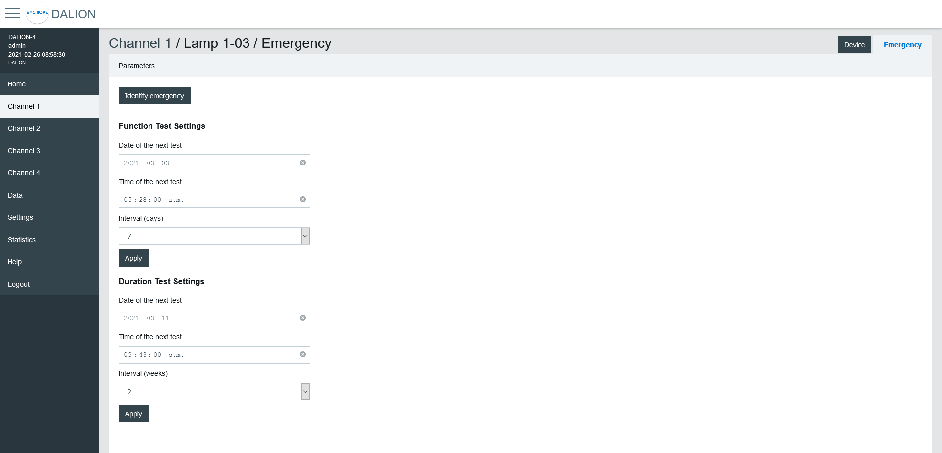
Identify emergency
Allows for the identification of the emergency lamp.
Function Test Settings
Allows the configuration of the interval for the function test.
Duration Test Settings
Allows the configuration of the interval for the duration test.
Prolong
Allows for the configuration of the prolong time.
Features
Show the features bits values.
Emergency Mode
Show the emergency mode bits value.
Emergency Status
Show the emergency status bits value.
Failure Status
Show the failure status bits value.
Timings
Show to values of the timings.
Other modes
Allows modifying the inhibit and rest modes.
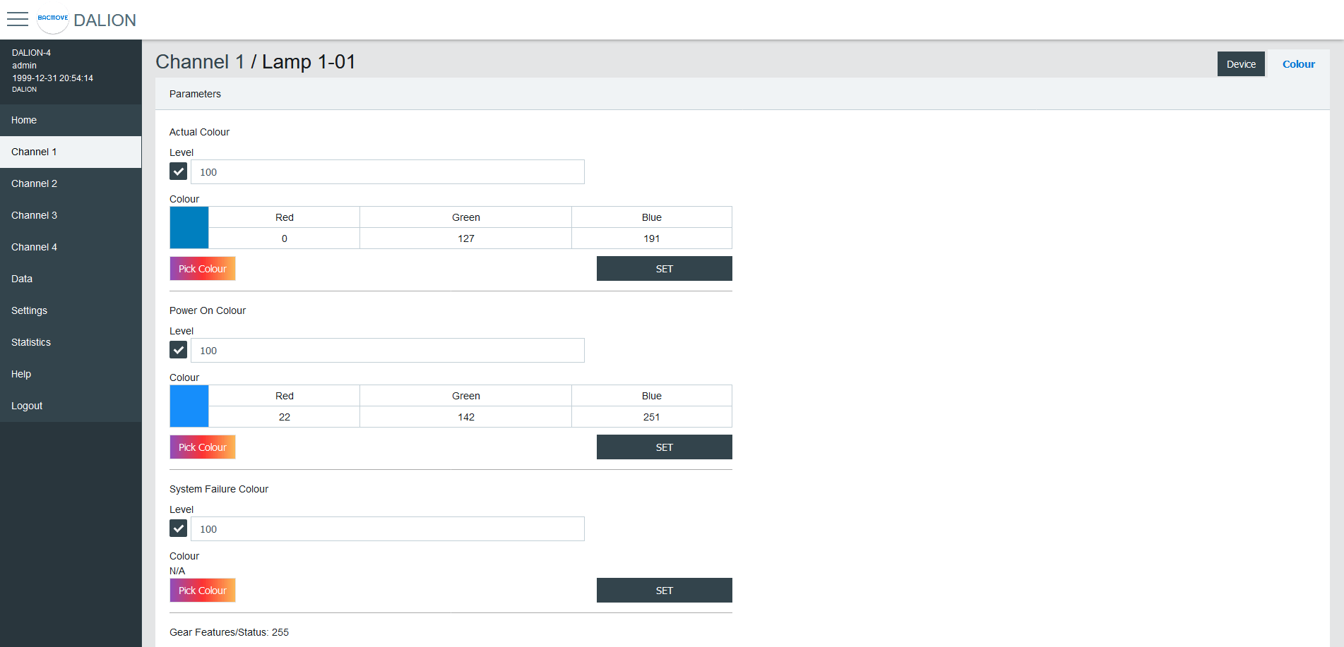
Colour Parameters
For the lamps with colour control, available with DALI Type 8 (DT8) lamps, other parameters are available. When colour parameters are available, a tab Colour is added.
| Name | Description |
|---|---|
| Actual Colour | Actual colour |
| Power On Colour | Colour after a power on |
| System Failure Colour | Colour when system failure |
| Gear Features/Status | DALI features of the lamp |
| Colour Type Features | DALI colour features of the lamp |
| Scenes 1-16 | Colour for the scenes 1 to 16 |
| Tc Warmest Kelvin (1) | Warmest colour temperature in Kelvin |
| Tc Coolest Kelvin (1) | Coolest colour temperature in Kelvin |
| Tc Physical Warmest (1) | Physical warmest colour temperature in Kelvin |
| Tc Physical Coolest (1) | Physical coolest colour temperature in Kelvin |
| RGBWAF Control (2) | RGBWAF Control |
| RGBWAF Assigned Colour (2) | RGBWAF Assigned Colour |
(1) Only available for lamps with the colour type; colour temperature Tc.
(2) Only available for lamps with the colour type; RGBWAF.
Colour Picker
When using Set Colour menu or the Pick Colour button a window appear to allow choosing the desired colour.
The window allows defining the colour according to the types of colours available for the selected lamp.
When a value is MASK, this value is not modified.
For example, it is possible to set only the green colour, without affecting the red and blue colour.
xy-Coordinate
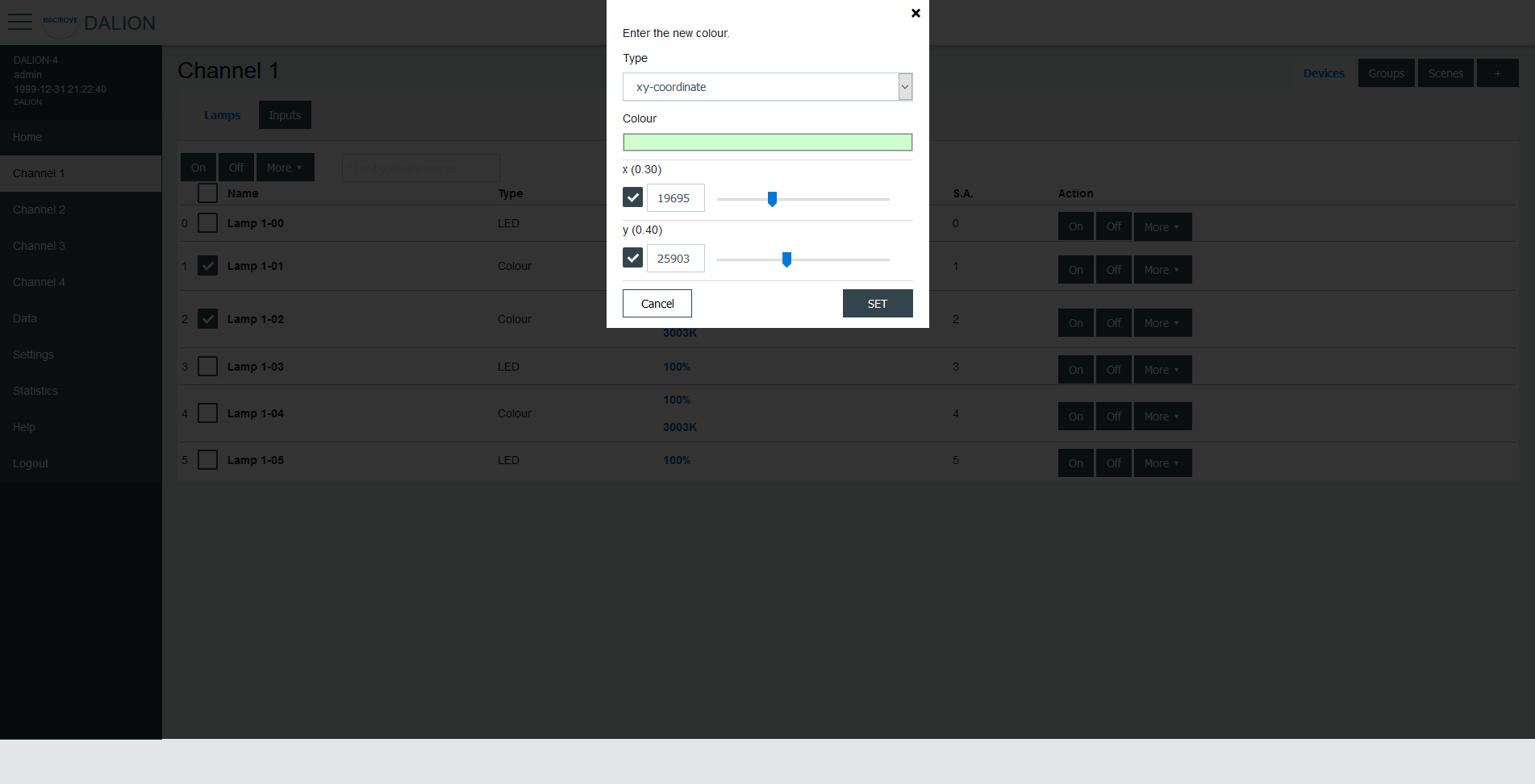
| Name | Unit | Minimum | Maximum | Default | Description |
|---|---|---|---|---|---|
| Colour Preview (1) | RGB | Clicking on the colour will open the browser colour picker. | |||
| x | 1 / 65536 | 0 | 65534 | ||
| y | 1 / 65536 | 0 | 65534 |
(1) Colour is for demonstration purposes only, the resulting lamp colour may be different.
colour temperature Tc
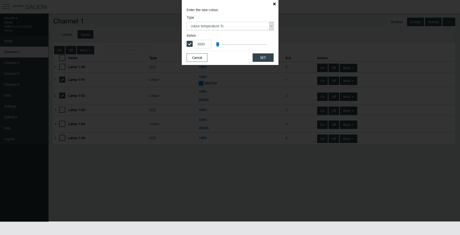
| Name | Unit | Minimum | Maximum | Default | Description |
|---|---|---|---|---|---|
| Kelvin | Kelvin | 16 (1) | 1 000 000 (1) | Colour temperature in Kelvin |
(1) The minimum and maximum Kelvin are also limited by the warmest and coolest parameters.
primary N
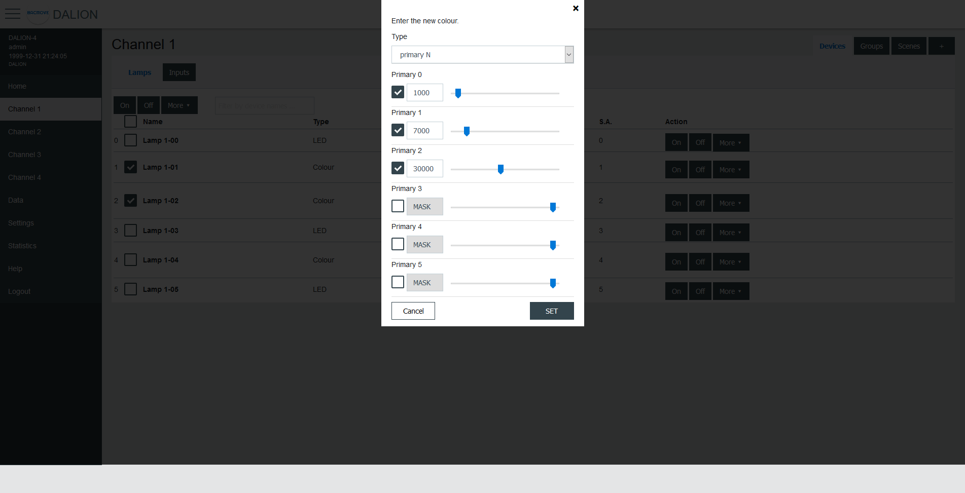
| Name | Unit | Minimum | Maximum | Default | Description |
|---|---|---|---|---|---|
| Primary 0-5 | 0 | 65534 | Primay value |
RGBWAF
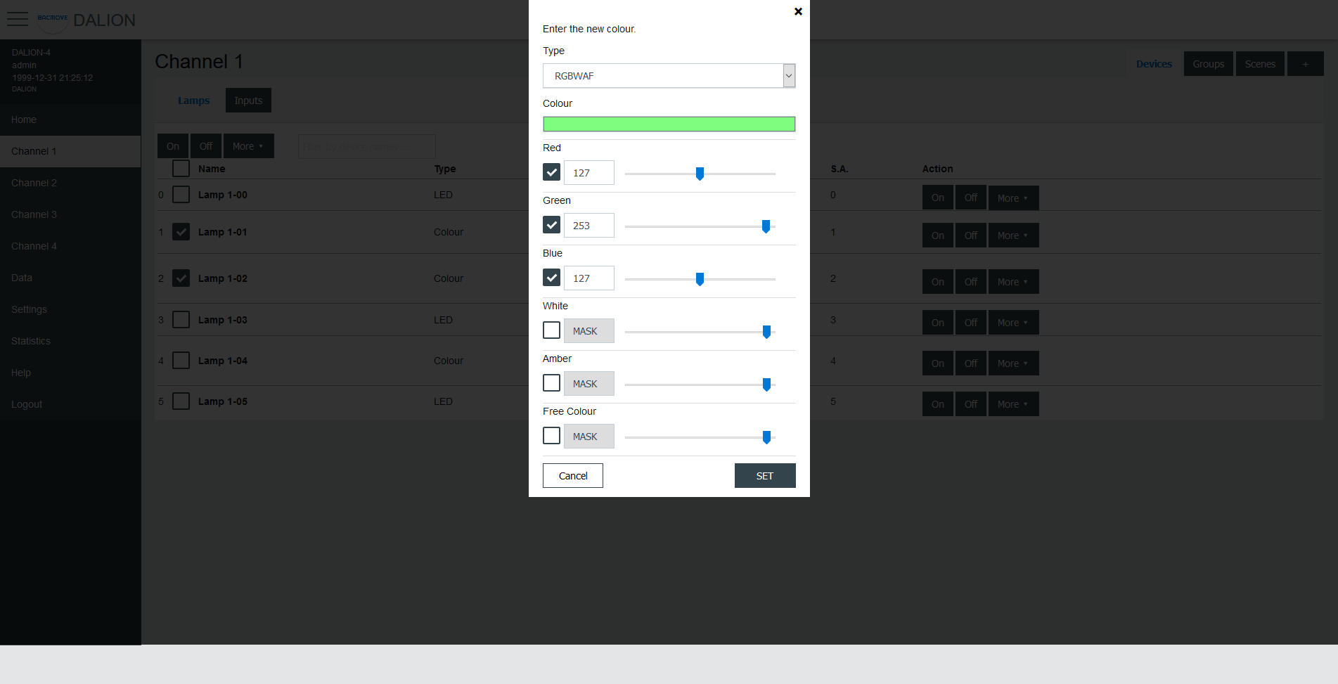
| Name | Unit | Minimum | Maximum | Default | Description |
|---|---|---|---|---|---|
| Colour Preview (1) | RGB | Clicking on the colour will open the browser colour picker. | |||
| Red | 0 | 254 | Red colour value | ||
| Green | 0 | 254 | Green colour value | ||
| Blue | 0 | 254 | Blue colour value | ||
| White | 0 | 254 | White colour value | ||
| Amber | 0 | 254 | Amber colour value | ||
| Freecolour | 0 | 254 | Freecolour colour value |
(1) Colour is for demonstration purposes only, the resulting lamp colour may be different.
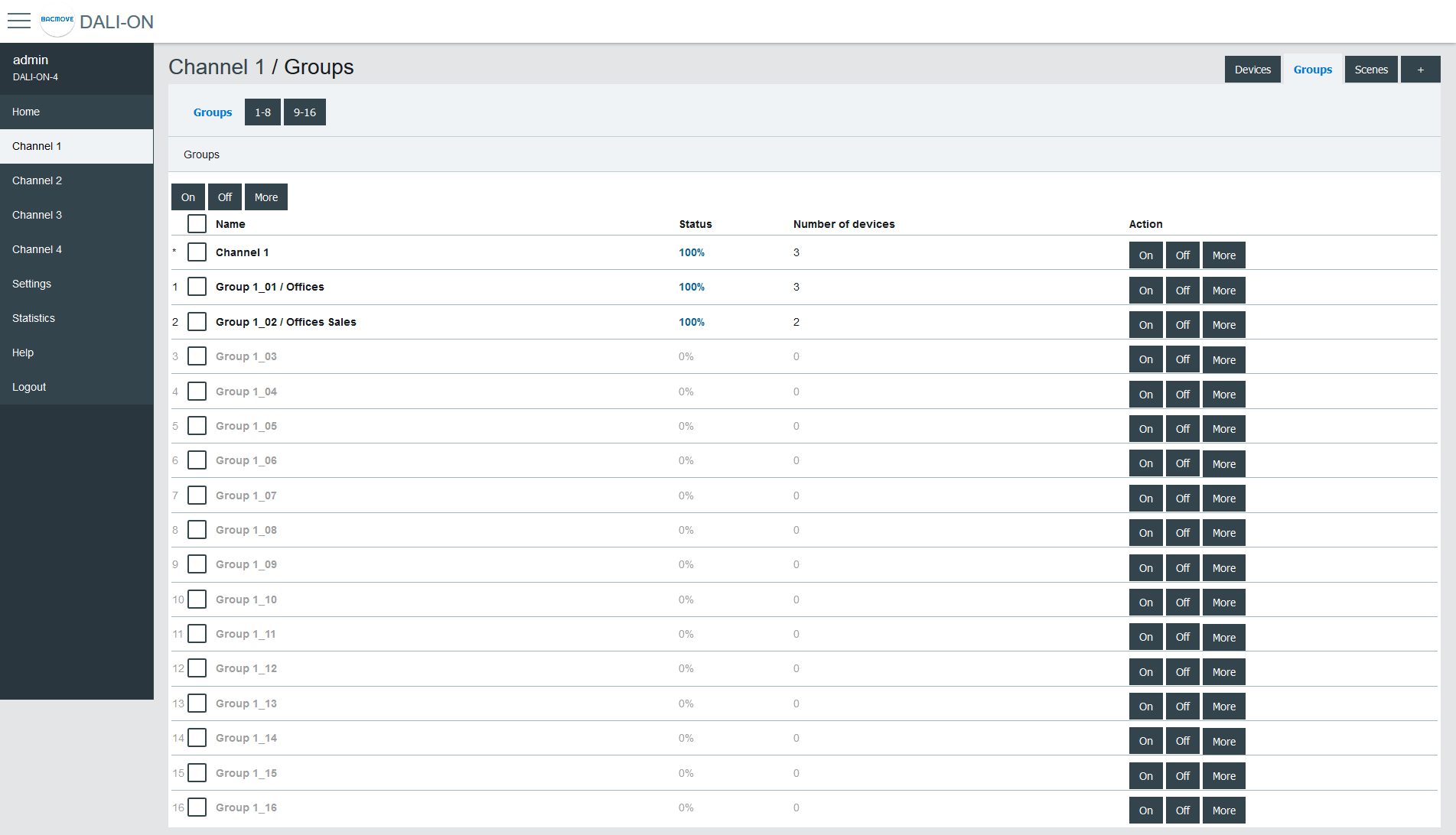
Groups
There are 16 groups for the lamps and each lamp can be part of any combination of the 16 groups. This page allows visualization and control of the groups.
The first line is indicated by a * and is the channel. The underlying lines are numbered for the 16 groups.
It is possible to:
- turn On or Off the group
- Set Level of the group intensity
- Recall, Store and Delete the group scenes
By clicking on a group row, the Group Parameters page opens.
Group Parameters
This page allows the configuration of group parameters.
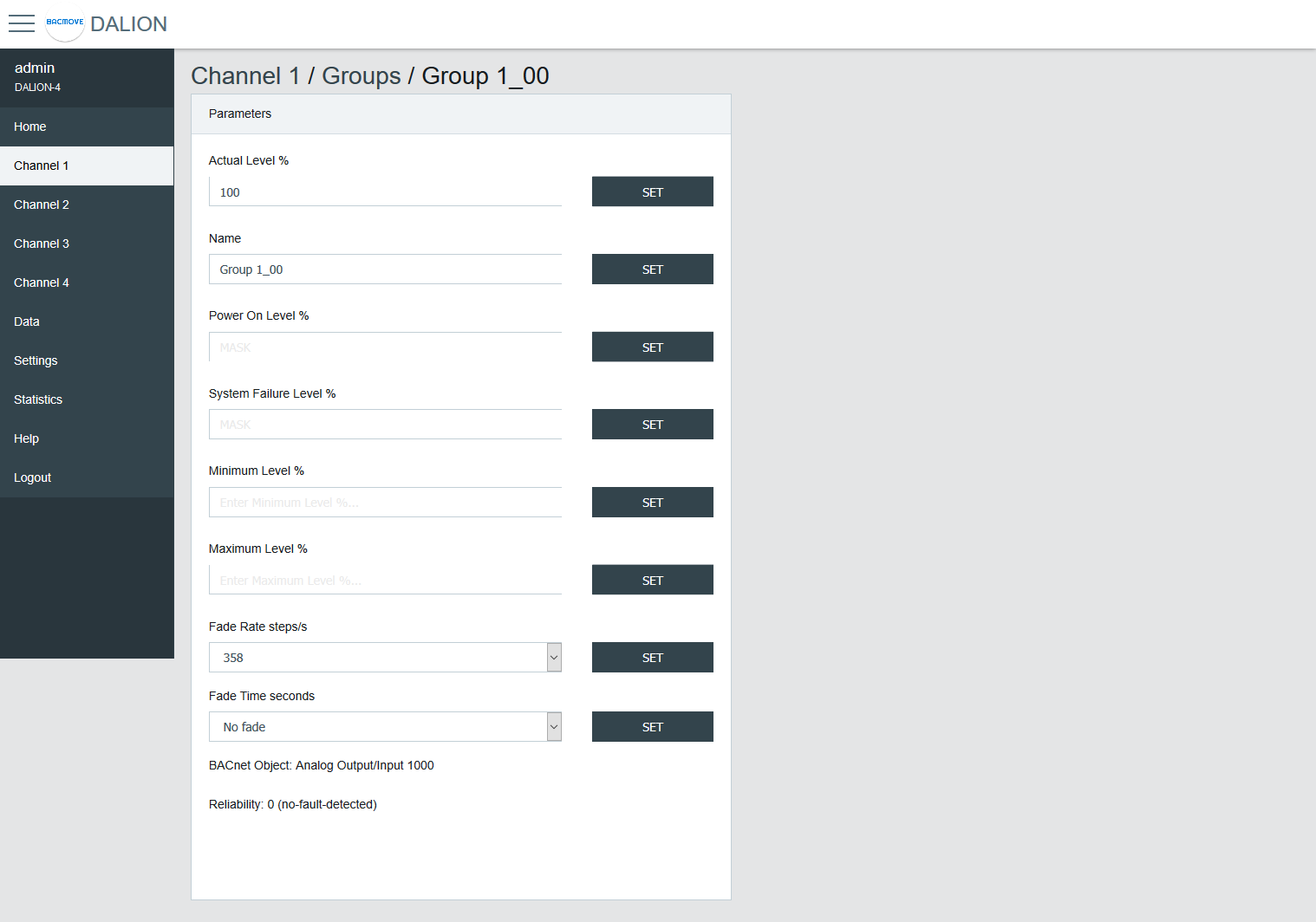
| Name | Unit | Minimum | Maximum | Default | Description |
|---|---|---|---|---|---|
| Actual Level | Percent | 0% | 100% | Actual group intensity | |
| Name | String | 32 characters | Name of the group | ||
| BACnet Object | String | BACnet object identifier of the group | |||
| Reliability | String | BACnet reliability of the group object | |||
| BAS Timeout Command | Choice | No Command | The command executed when communication is lost with another BACnet device (BAS). No Command, Off, On or Timeout Level. |
Group names provide textual identification for each group. The intensity level of the groups can be changed. Once it is modified, all lamps in the group must reach the same brightness level.
Certain parameters of the DALI lamps can be sent to all the lamps which are part of the group.
| Name | Unit | Minimum | Maximum | Default | Description |
|---|---|---|---|---|---|
| Power On Level | Percent | 0% | 100% | 100% | Level of intensity after a power on |
| System Failure Level | Percent | 0% | 100% | 100% | Level of intensity when system failure |
| Minimum Level | Percent | 0.1% | 100% | 100% | Minimum level of intensity |
| Maximum level | Percent | 0.1% | 100% | 100% | Maximum level of intensity |
| Fade Rate | Choice | 2.8 | 358 | 44.7 | Fade rate in steps per second |
| Fade Time | Choice | No Fade | 90.5 | No Fade | Fade time in seconds |
| Dimming Curve | Choice | Logarithmic | Linear | Logarithmic | Dimming curve |
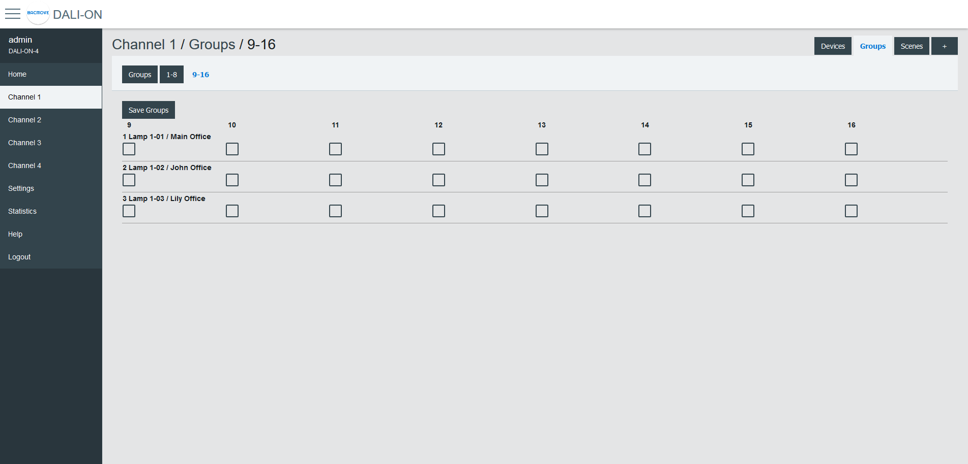
Groups 0-7 / 8-15
For easy visualization and assignment of the 16 groups, they are separated in views of eight groups (i.e., Groups 0-7 and Groups 8-15).

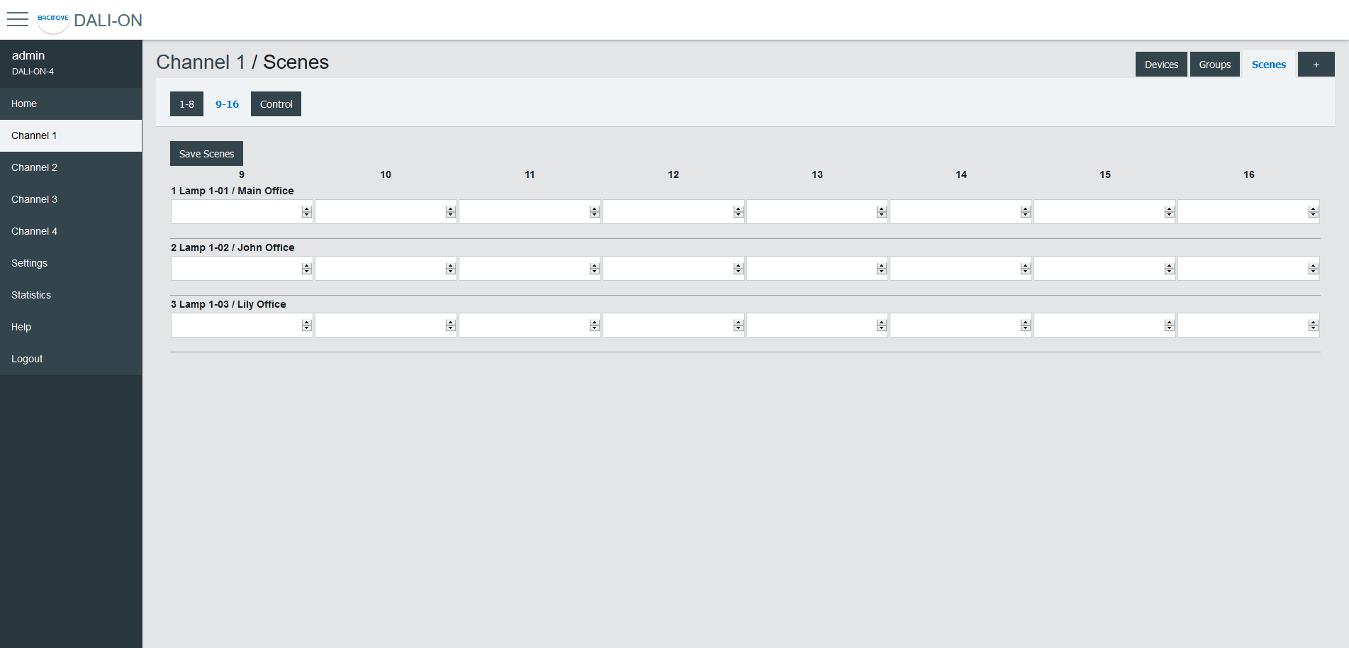
Scenes
Each lamp has 16 scenes. A scene is a level of light intensity in percentages. The value of a scene can also be left empty. Scenes control can be sent to a single lamp, a group of lamps, or the entire DALI channel. When a scene is recalled, all the addressed lamps are invited to dim their brightness at the same brightness level.
For lamps with colour control (i.e., DT8), the 16 scenes can also recall the colour levels. The configuration of the scene colour levels should be performed in the Colour page of each lamp.
Scenes Control
Scenes can be recalled, stored or deleted. Once the desired group or broadcast destination is selected and the Recall, Store or Delete action is also selected, one of the 16 scenes can be performed.
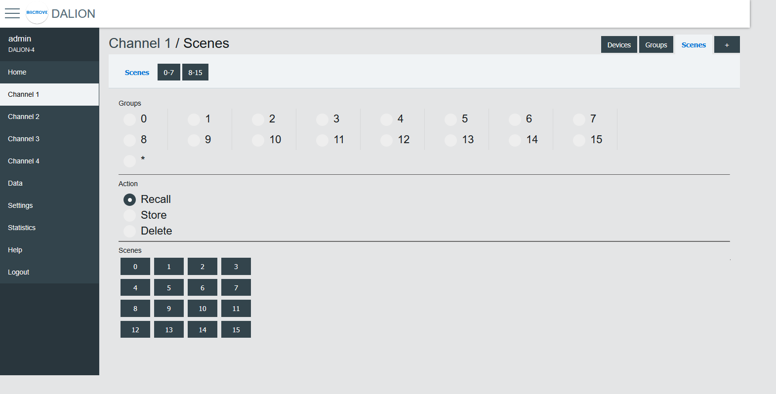
Scenes 0-7 / 8-15
For easy visualization and configuration of the 16 scenes, they are separated in views of eight scenes (i.e., Scenes 0-7 and Scenes 8-15).

Memory Bank
This page allows read, editing and writing DALI memory banks of lamps and DALI-2 input devices.
Inputs
This page displays the list of commissioned DALI light sensors, occupancy sensors and buttons. The list provides a descriptive Name of each input device as well as other information like occupancy state, light value, types and short address.
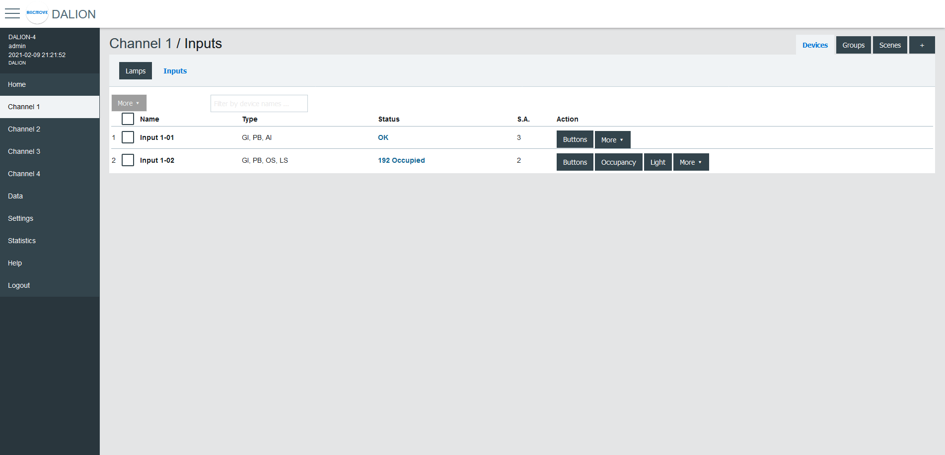
Inputs devices can identify themselves with the Identify button.
The 🛇 icon indicates that Buttons or Occupancy commands are prohibited. See the network properties Allowed_Command or Buttons_Allowed_Command for more information.
By clicking on an input row, the Input Parameters page opens.
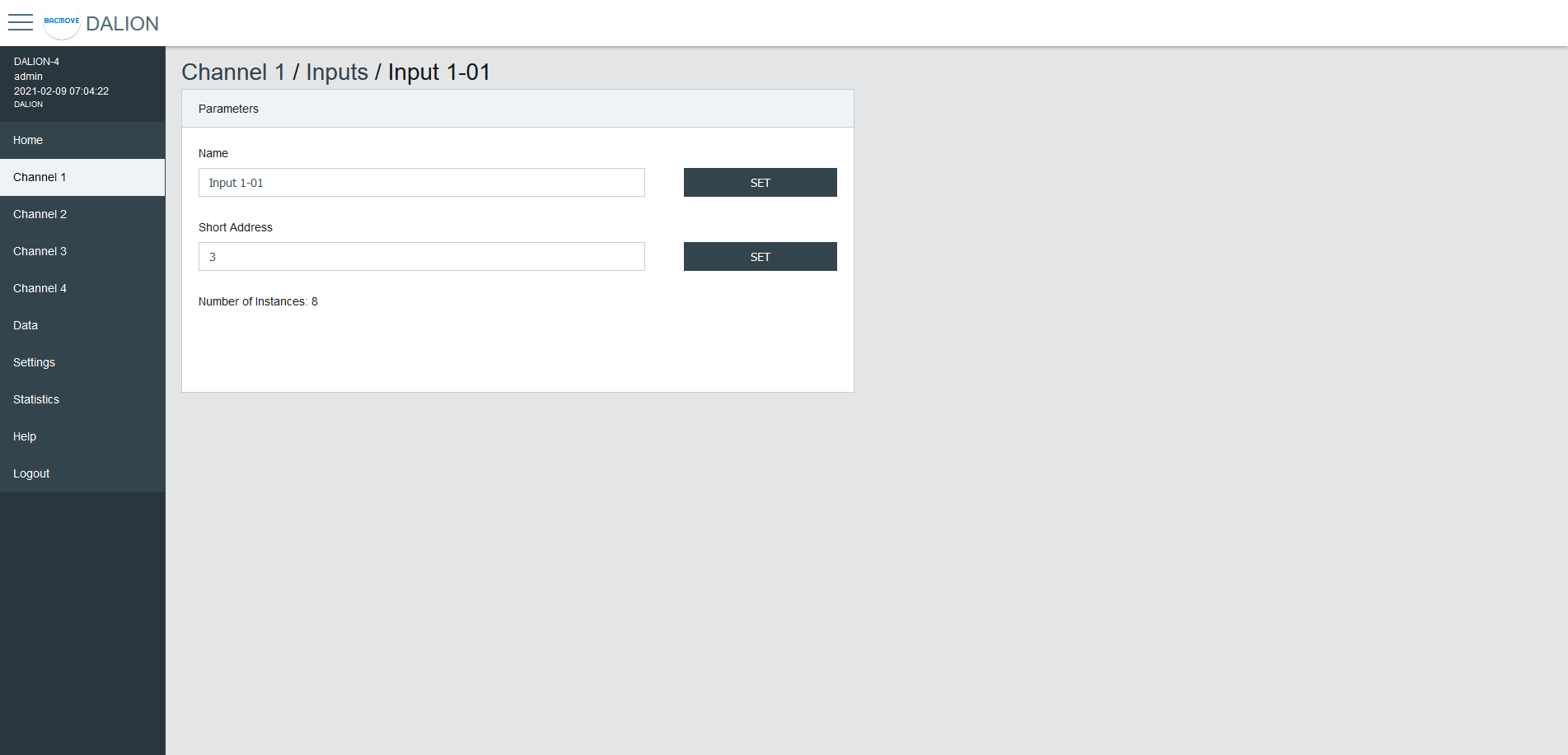
Input Parameters
This page allows the configuration of input parameters.
Parameters
| Name | Unit | Minimum | Maximum | Default | Description |
|---|---|---|---|---|---|
| Name | String | 32 characters | Name of the device | ||
| Short Address | Number | 0 | 63 | The short address | |
| Number of instances | Number | 1 | 32 | Displays the number of instances |
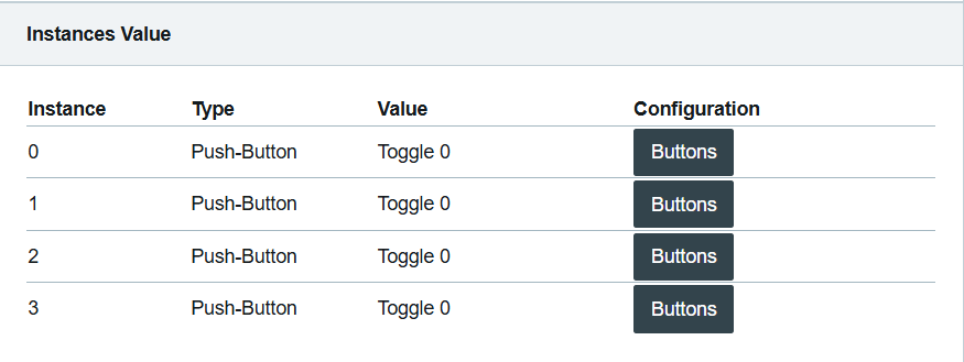
Instances Value
Display of the values of the input instances.
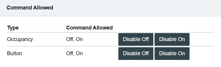
Command Allowed
Display and modification of the allowed commands for the occupation and button inputs.
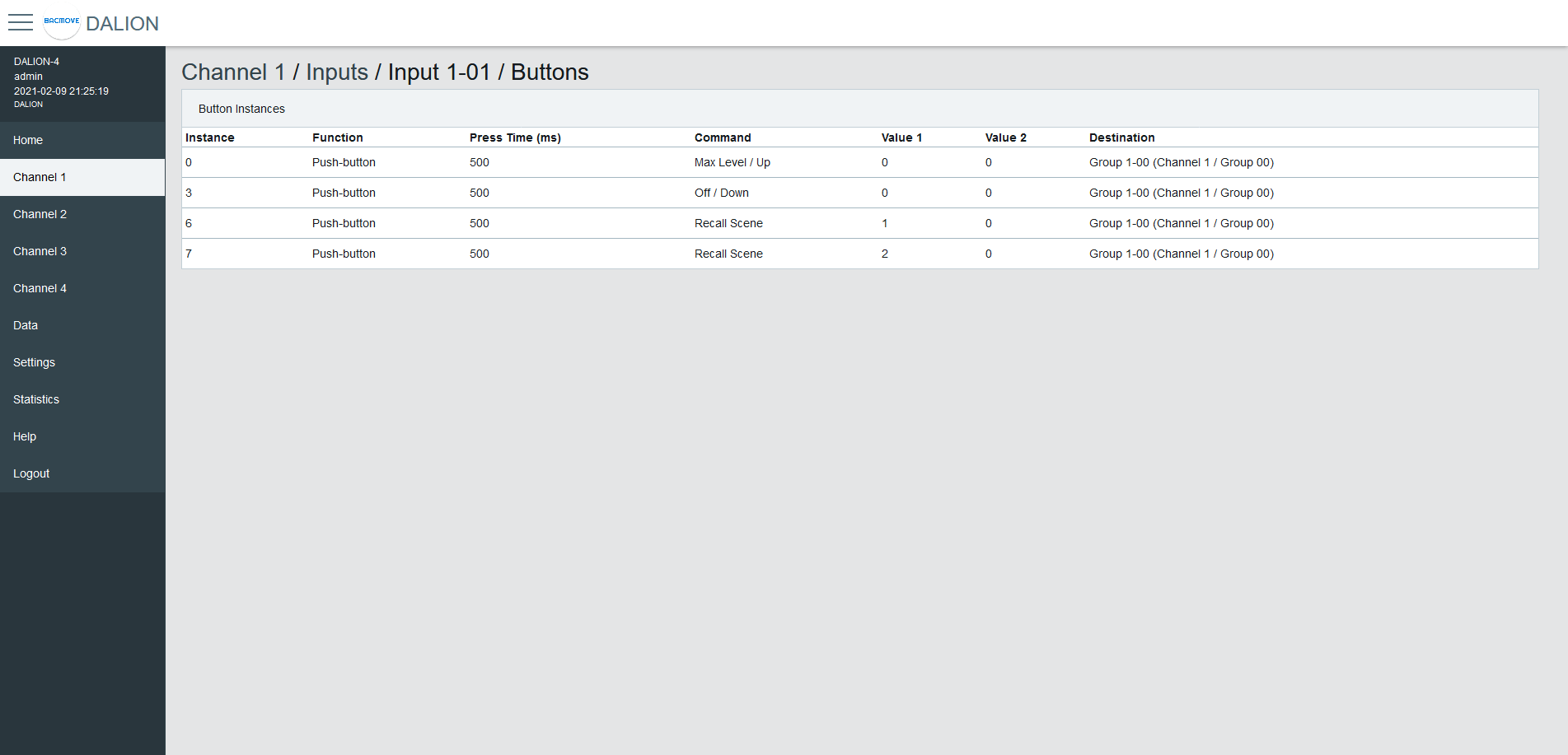
Buttons
Each input device support up to 32 button instances. The command and destination for each instance are configurable by clicking on an instance row.
Button Parameters
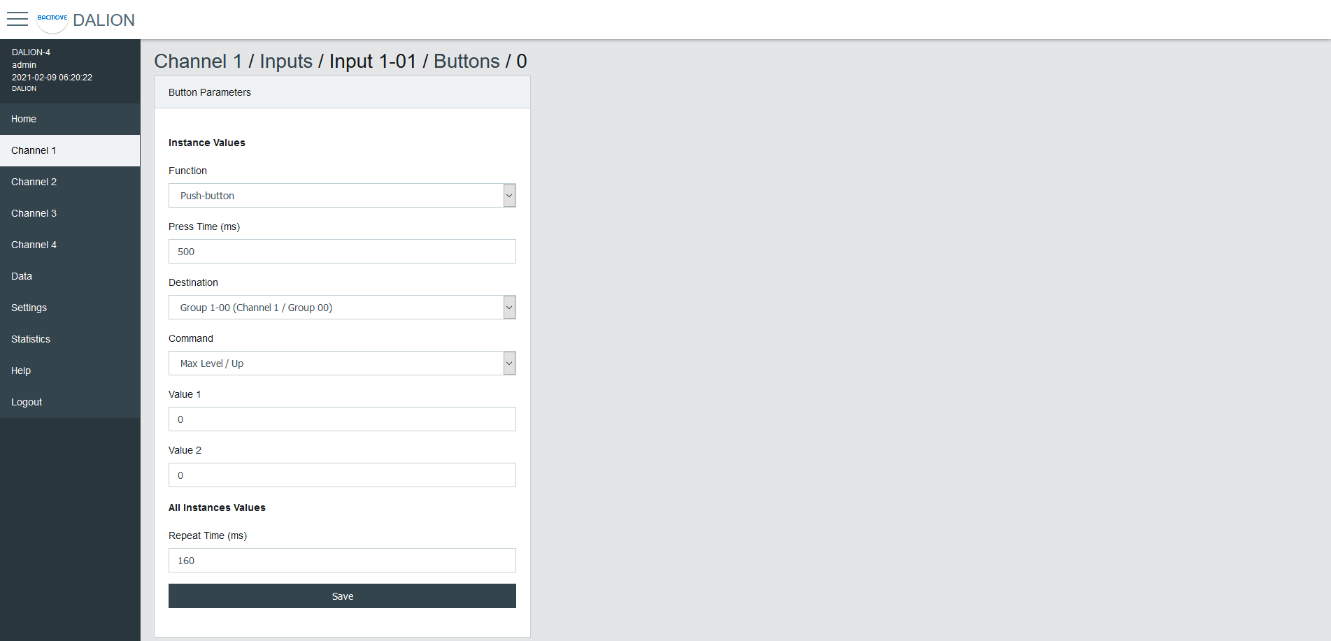
| Name | Description |
|---|---|
| Function | Push-button or Switch |
| Press Time | Press time in milliseconds |
| Destination Type | Type of the Destination |
| Destination | Destination of the command |
| Command | Choice of the button command |
| Value 1 | First value of the command |
| Value 2 | Second value of the command |
Function
| Name | Description |
|---|---|
| Push-button | Actuated when the button is temporarily pressed |
| Switch | Actuated when the button position is toggled |
Push-button for momentary contact, like a wall push button.
Switch for maintained contact, like an occupancy sensor or a photocell.
Press Time
The time in milliseconds before registering a button press.
Repeat Time (ms)
The time in milliseconds between repeated commands. This parameter is the same for all instances of the same device.
Destination Type
The destination type allows to determine wich destinations and commands are available to the button configuration.
| Name |
|---|
| Group, Channel, RLC |
| Lamp |
| Commander |
| Commanders |
Group, Channel, RLC
Allows commanding a DALI group, a DALI channel, or a Room Light Control.
Room Light Control commands are prefixed with "RLC:".
Lamp
Allows commanding a DALI lamp.
Commander
Allows starting or stopping a Commander.
Commanders
Allows starting or stopping a Commander.
Destination
The destination depends on the selected Destination Type.
Command - Group, Channel, RLC, Lamp
Push-button
| Name | Short Press | Long Press | Long Press Repeat |
|---|---|---|---|
| Disabled | |||
| Direct Value | Direct Value Value 1 % | ||
| On | Recall Max Level | ||
| On / Up | Recall Max Level | On and Step Up | Up |
| Off | Off | ||
| Off / Down | Off | Step Down and Off | Down |
| Min Level | Min Level | ||
| Min Level / Down | Min Level | Step Down and Off | Down |
| Recall Scene | Recall Scene Value 1 0-15 | ||
| Recall Scene / Up | Recall Scene Value 1 0-15 | On and Step Up | Up |
| Recall Scene / Down | Recall Scene Value 1 0-15 | Step Down and Off | Down |
| On / Off | Toggle between Recall Max Level and Off | ||
| Last Level | Recall Last Level | ||
| Last Level / Up | Recall Last Level | On and Step Up | Up |
| Last Level / Off | Toggle between Last Level and Off | ||
| On / Off, Up / Down | Toggle between Recall Max Level and Off | Toggle between On and Step Up and Step Down and Off | Toggle between Up and Down |
| Last Level / Off, Up / Down | Toggle between Recall Last Level and Off | Toggle between On and Step Up and Step Down and Off | Toggle between Up and Down |
| Direct Value / Off, Up / Down | Toggle between Direct Value Value 1 % and Off | Toggle between On and Step Up and Step Down and Off | Toggle between Up and Down |
| Recall Scene / Off, Up / Down | Toggle between Recall Scene Value 1 0-15 and Off | Toggle between On and Step Up and Step Down and Off | Toggle between Up and Down |
| RLC: Occupancy - Unoccupied | Toggle occupancy state, 1 is unoccupied. | ||
| RLC: Occupancy - Occupied | Toggle occupancy state, 1 is occupied | ||
| RLC: Daylight Harvesting - Stop | Stop daylight harvesting | ||
| RLC: Daylight Harvesting - Start | Start daylight harvesting | ||
| RLC: Demand Response - Stop | Stop demand response | ||
| RLC: Demand Response - Start | Start demand response |
Switch
| Name | Open switch | Close switch |
|---|---|---|
| Disabled | ||
| Direct Value | Direct Value Value 2 % | Direct Value Value 1 % |
| On | Recall Max Level | |
| On / Up | Recall Max Level | |
| Off | Off | |
| Off / Down | Off | |
| Min Level | Min Level | |
| Min Level / Down | Min Level | Min Level |
| Recall Scene | Recall Scene Value 1 0-15 | Recall Scene Value 2 0-15 |
| Recall Scene / Up | Recall Scene Value 1 0-15 | Recall Scene Value 2 0-15 |
| Recall Scene / Down | Recall Scene Value 1 0-15 | Recall Scene Value 2 0-15 |
| On / Off | Off | On |
| Last Level | Recall Last Level | |
| Last Level / Up | Recall Last Level | |
| Last Level / Off | Off | Recall Last Level |
| On / Off, Up / Down | Off | On |
| Last Level / Off, Up / Down | Off | Recall Last Level |
| Direct Value / Off, Up / Down | Off | Direct Value Value 1 % |
| Recall Scene / Off, Up / Down | Off | Recall Scene Value 1 0-15 |
| RLC: Occupancy - Unoccupied | Occupied | Unoccupied |
| RLC: Occupancy - Occupied | Unoccupied | Occupied |
| RLC: Daylight Harvesting - Stop | Start daylight harvesting | Stop daylight harvesting |
| RLC: Daylight Harvesting - Start | Stop daylight harvesting | Start daylight harvesting |
| RLC: Demand Response - Stop | Start demand response | Stop demand response |
| RLC: Demand Response - Start | Stop demand response | Start demand response |
Command - Commander
| Name | Short Press | Long Press | Long Press Repeat |
|---|---|---|---|
| No Command | |||
| Start | Start the commander in the Destination | ||
| Stop | Stop the commander in the Destination |
Command - Commanders
| Name | Short Press | Long Press | Long Press Repeat |
|---|---|---|---|
| No Command | |||
| Start Commander NN | Start the commander NN | ||
| Stop Commander NN | Stop the commander NN |
Value 1
First value of the command.
Value 2
Second value of the command.
Occupancy Sensor
Each input device supports up to one occupancy sensor instance.
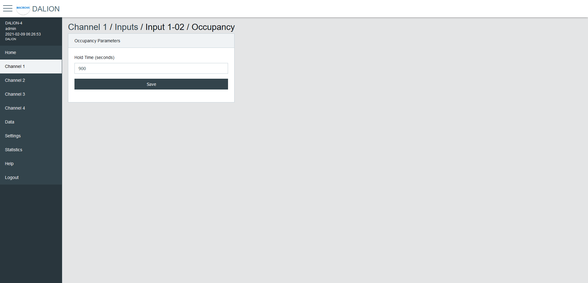
| Name | Unit | Minimum | Maximum | Default | Description |
|---|---|---|---|---|---|
| Hold Time | Seconds | Hold time in seconds |
Light Sensor
Each input device supports up to one light sensor instance.
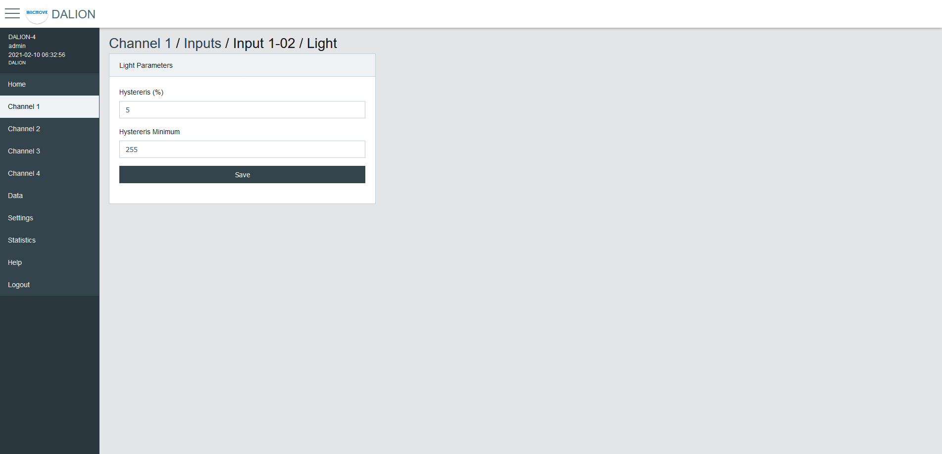
| Name | Unit | Minimum | Maximum | Default | Description |
|---|---|---|---|---|---|
| Hysteresis | Hysteresis in percentage | ||||
| Hysteresis Minimum | Hysteresis minimum |
To prevent flooding the DALI network with an excessive number of events triggered by minor changes in illuminance levels, a hysteresis band is present in the light sensor.
The hysteresis band is determined as the greater of the following values:
The Hysteresis in percentage of the sensor internal current illuminance level.
The Hysteresis Minimum.
Hysteresis
This is a percentage of the current sensor internal illuminance level.
The valid values are from 0 to 25 percent.
Hysteresis Minimum
The minimum hysteresis.
The valid values are from 0 to 255.
Light Sensor Calibration
Light sensor calibration involves using a lux meter to measure the ambient light intensity. By comparing the value of the sensor with the lux meter reading, you can adjust the sensor to ensure accurate and consistent measurements. This process ensures that the output of the sensor corresponds accurately to the actual light intensity in lux.
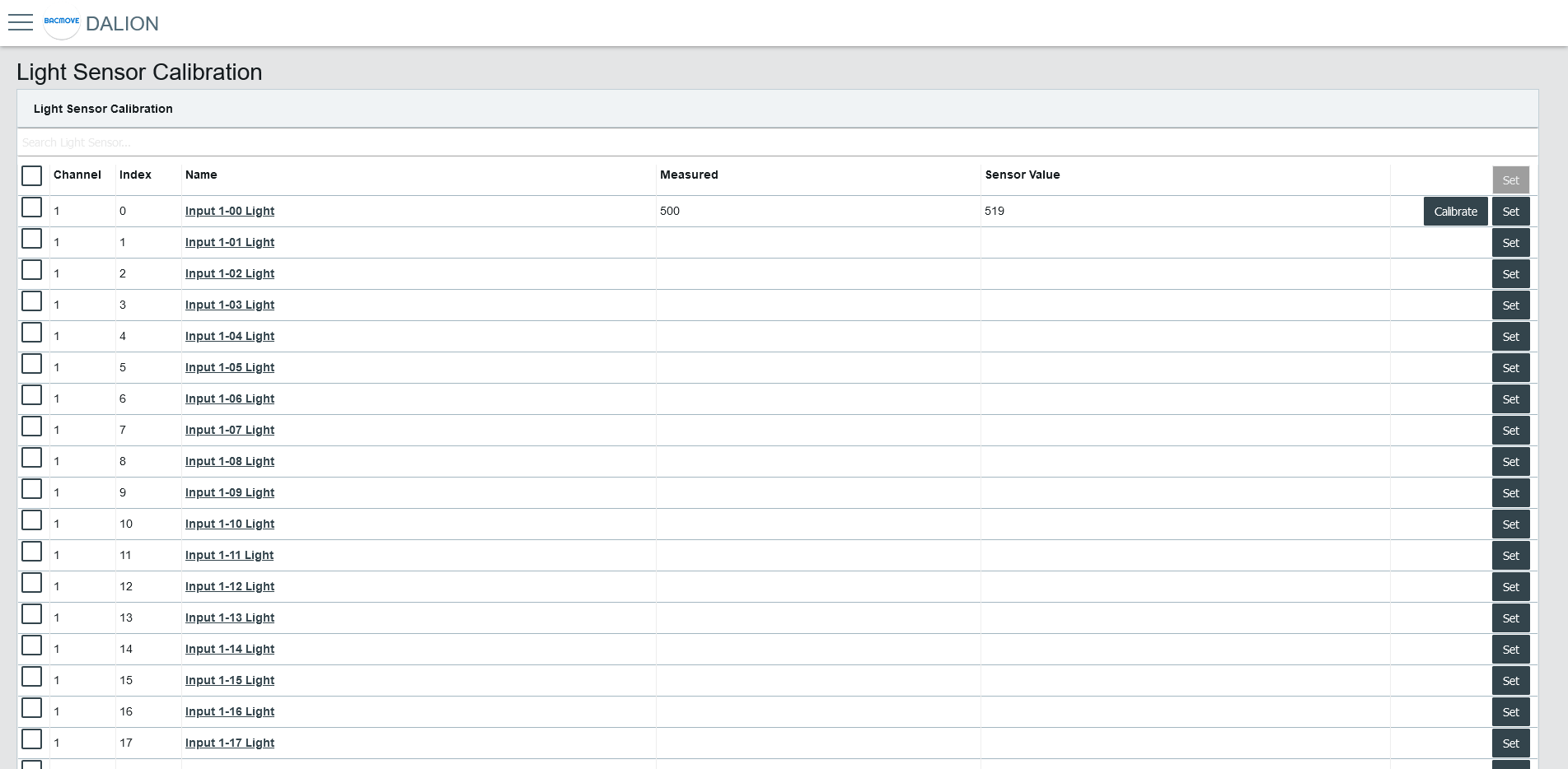
Light Sensors List
It list the calibration for each light sensor.
Collumns
####### Checkbox
Allows the manual calibration of the multiple selected light sensors.
####### Channel
The light sensor channel number, 1 to 4.
####### Index
The light sensor index number, 0 to 31.
####### Name
The light sensor name.
####### Measured
The value measured with a lux meter for calibration.
####### Sensor Value
The light sensor reading value used for calibration.
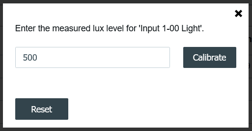
####### Calibrate Button
Opens the light sensor calibration.
Enter the value obtained from the lux meter and press the Calibrate button.
The Reset button clears the calibration, allowing the use of the light sensor value without calibration.
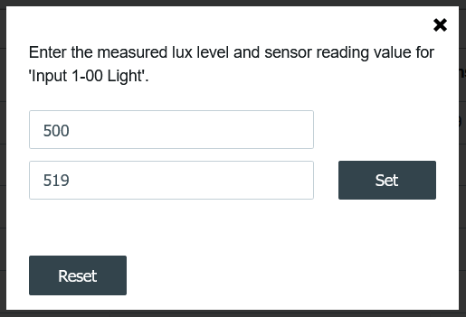
####### Set Button
Opens the manual calibration for the light sensor.
Enter the value obtained from the lux meter and the light sensor reading. Then, press the Set button.
The Reset button clears the calibration, allowing the use of the light sensor value without calibration.
Addition of DALI devices
The button "+" is used to search for non-commissioned devices.
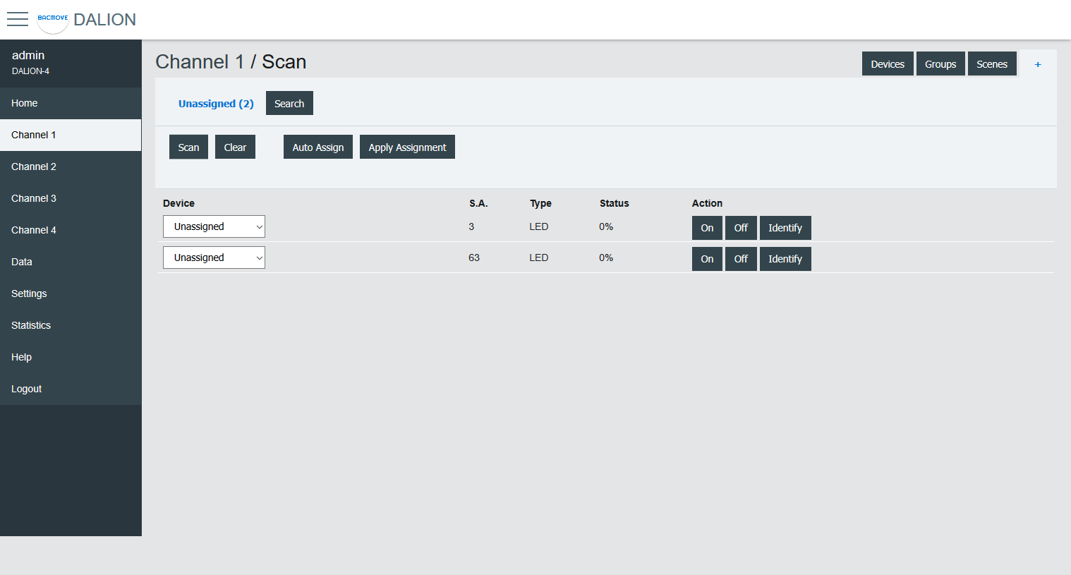
Unassigned Devices
After scanning a channel, the page displays the non-commissioned devices found on the network. The buttons allow turning On, Off and to Identify the lamp by cycling it between its minimum and its maximum of intensity.
The Scan button allows starting a scan on the DALI channel for unassigned devices.
The Clear button allows clearing the list of unassigned devices.
The Auto Assign button automatically assigns lamps to a lamp index.
The Apply Assignment button assign lamps to a selected lamp index.
Assignment
There are three ways of assigning the DALI devices.
Auto Assign
The lamps are automatically assigned to a lamp index.
Apply Assignment
The selected assignment is applied.
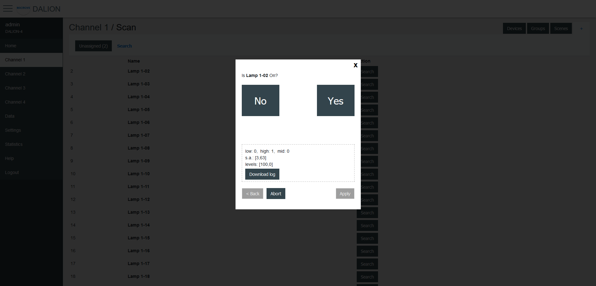
Search
The available lamps can be searched. By pressing the Search button next to a lamp, a search by a half-interval search means is launched to find the lamp. Half of the lamps are turned Off, while the other half is turned On, the user must answer No or Yes if the desired lamp is On. This process is repeated until only the desired lamp is On.
Once the search is complete, the user can enter a name for the lamp and Apply the assignment.
Data
Data Points
The BACnet objects are listed.
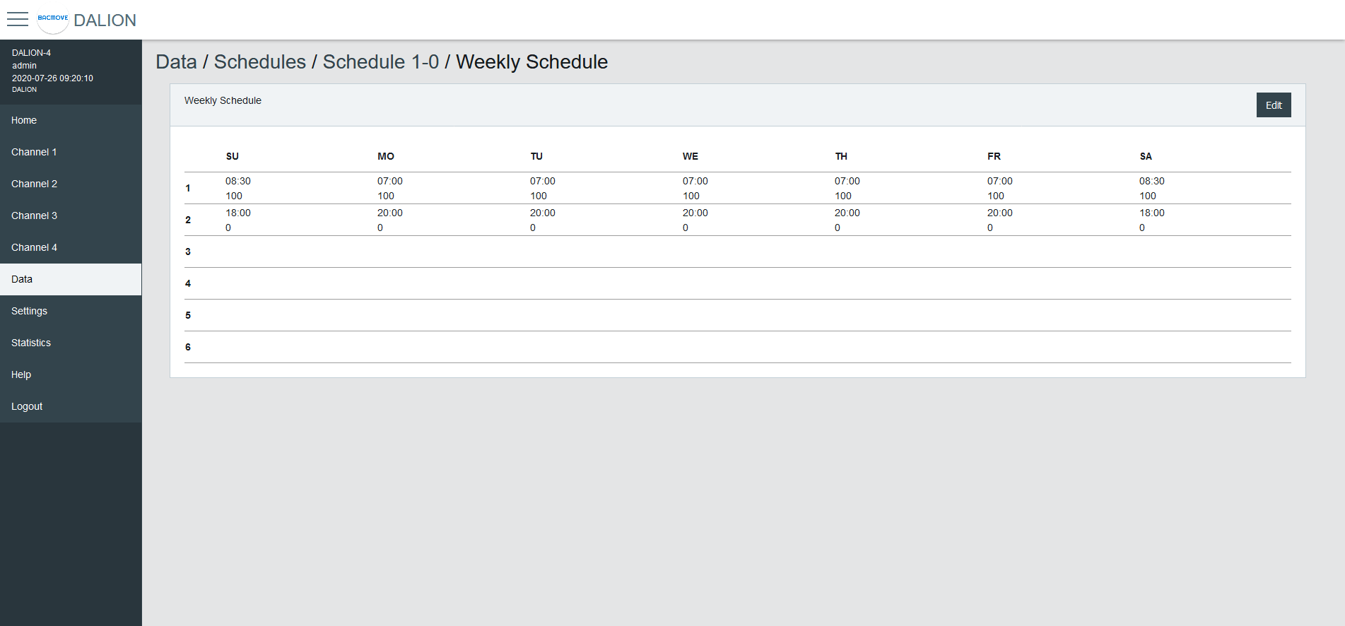
Schedules
The schedules allow to automatically adjust the light intensity at a specific time for the groups, channels and scene controllers.
There are 4 (4 DALI channels model), 1 (1 DALI channel model) schedules of 7 weekdays and each day can execute up to 6 different events. Each schedule can control up to 4 different data points.
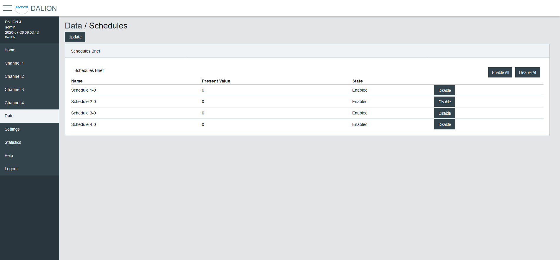
Schedules Brief
Displays the current values of the schedules and allows to Enable or Disable them.
Clicking on a schedule row allows to modify its parameters and events.
Schedule Parameters
Allows to modify the parameters of a schedule such as its name and its output data point.
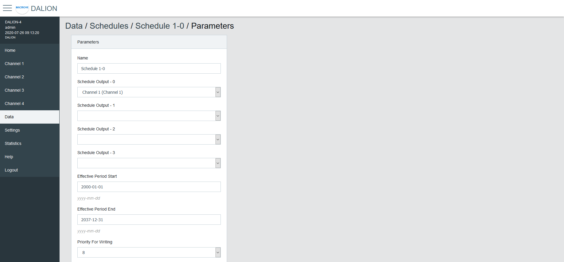
| Name | Unit | Minimum | Maximum | Default | Description |
|---|---|---|---|---|---|
| Name | String | 32 characters | Name of the schedule | ||
| Output Type | Choice | The type of output | |||
| Schedule Output 1 | Data Point | Data point where the schedule writes | |||
| Schedule Output 2 | Data Point | Data point where the schedule writes | |||
| Schedule Output 3 | Data Point | Data point where the schedule writes | |||
| Schedule Output 4 | Data Point | Data point where the schedule writes | |||
| Effective Period Start | Date | First date on which the schedule is in effect | |||
| Effective Period End | Date | Last date on which the schedule is in effect | |||
| Priority For Writing | Number | 1 | 16 | 8 | Priority used by the schedule when writing |
| Schedule Default | Number | Default value of the schedule | |||
| BACnet Object | String | BACnet object identifier of the schedule |
Output Type
Group, Channel
Allows sending command to a group or channel.
Commander
Allows sending command to a single commander.
Commanders
Allows sending command to a commander.
Weekly Schedule
Displays the scheduled events of the schedule.
Weekly Schedule Edit
Allows modifying the schedule events.
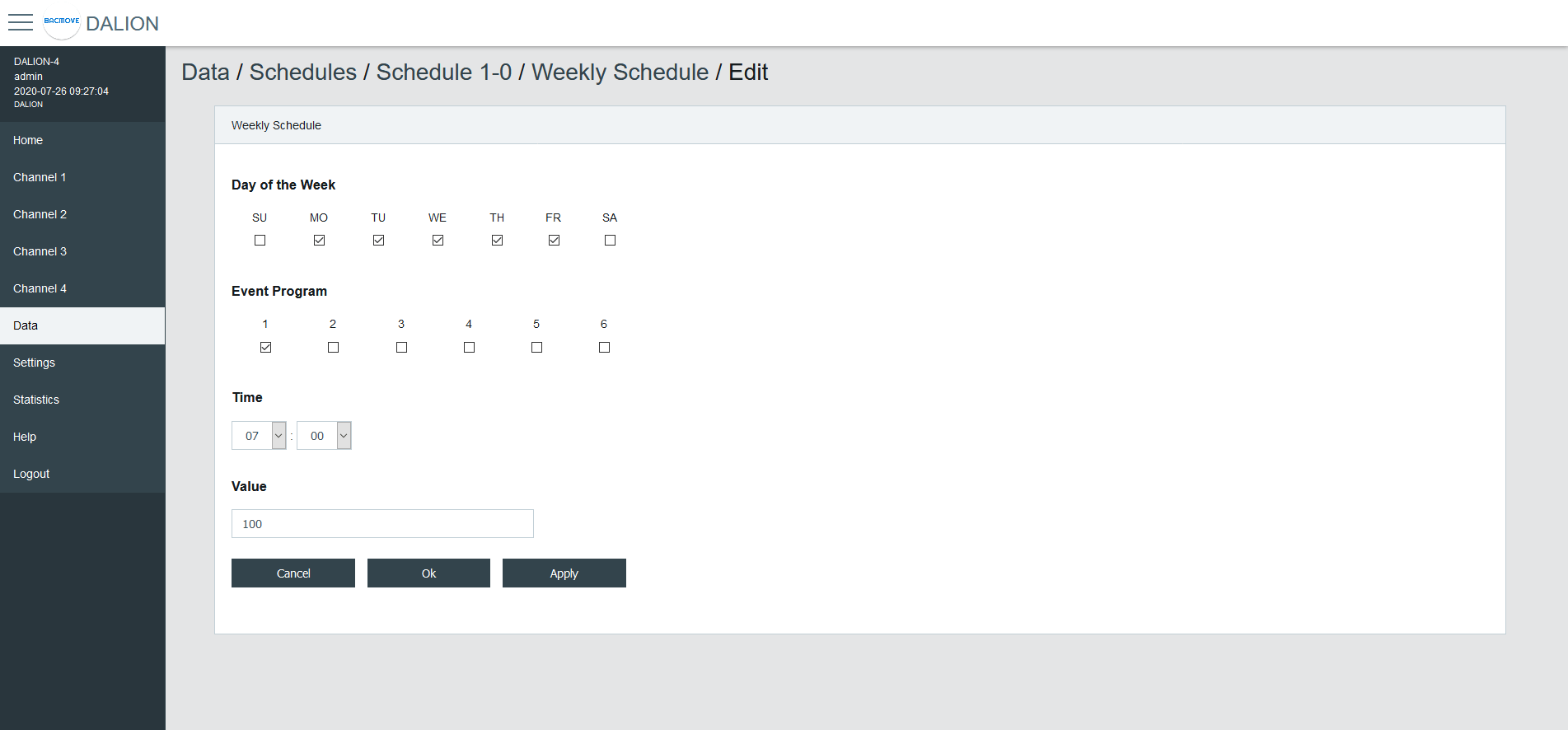
Day of the Week
Allows selecting the days of the week to modify. Several days can be modified at the same time.
Event Program
Allows selecting the event program to modify.
Type
The type of event time.
| Type | Description |
|---|---|
| Time | Fixed time |
| Sunrise | Astronomical sunrise time |
| Sunset | Astronomical sunset time |
Time
The time of the event.
By Selecting -- : -- the events corresponding to the selected Day of the Week and Event Program will be deleted.
Offset
For astronomical time allows for an offset of 120 minutes before or after the astronomical time.
Earliest Time
For astronomical time allows limiting the earliest time that the event can occur.
Execute Earliest
For astronomical time allows executing the event if it were to occur before the Earliest Time.
Latest Time
For astronomical time allows limiting the latest time that the event can occur.
Execute Latest
For astronomical time allows executing the event if it were to occur after the Latest Time.
Value
The value written by the schedule at the specified time.
Buttons
The Ok button applies the modification of the schedule events and returns to the Weekly Schedule page. The button Apply applies the modification but remains on the same page to allow the entry of more events. The button Cancel returns to the Weekly Schedule page without modifying the events.
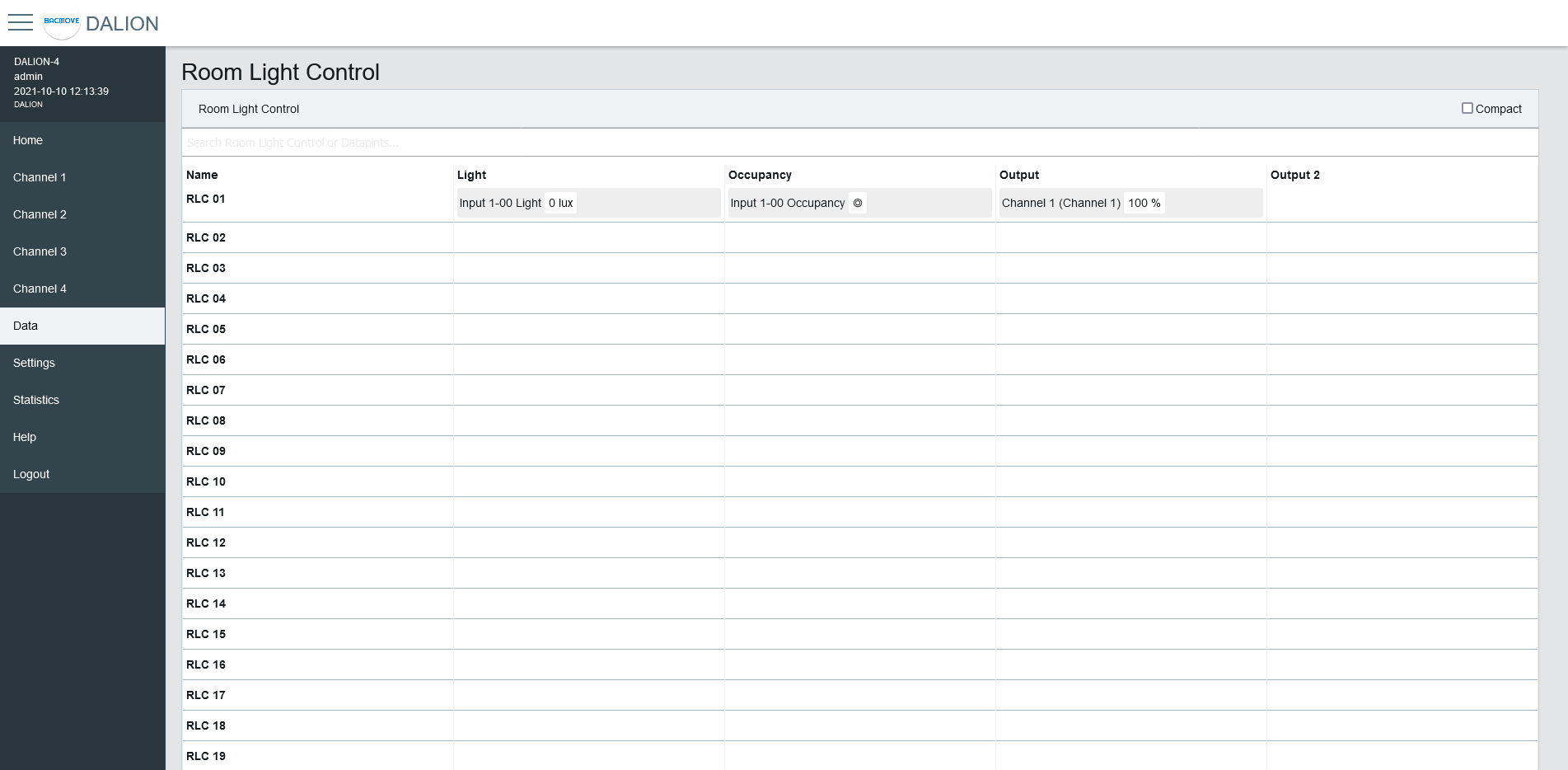
Room Light Control
The Room Light Control allow to automatically adjust the light intensity depending of external inputs such as occupancy, presence and light sensors.
Room Light Control List
Lists all the available Room Light Control. It also indicates the current states of the occupancy, light sensors and outputs.
Clicking on a Room Light Control row allows to modify its parameters.
Room Light Control Parameters
Allows to modify the parameters of a Room Light Control such as its name, its timings and its output data points.
Refer to the associated BACnet object for further details.
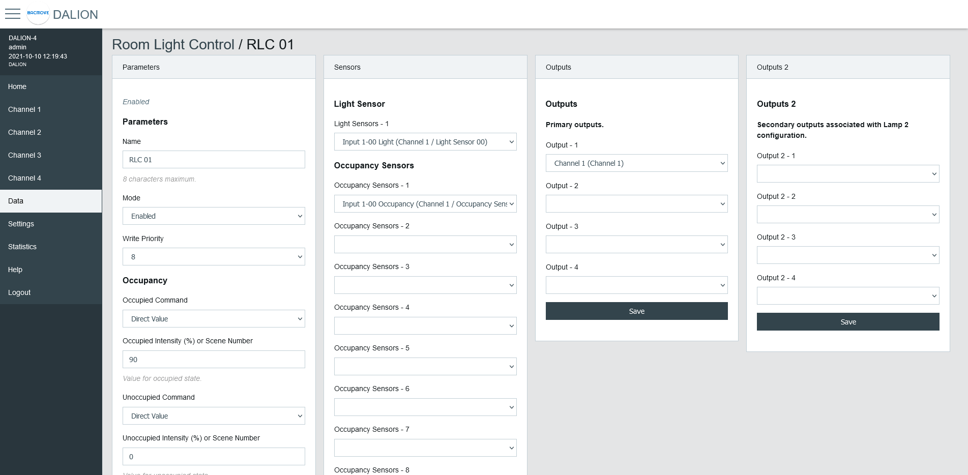
Parameters
| Name | Unit | Limit | Default | Description |
|---|---|---|---|---|
| Name | String | 8 characters | RLC NN, where NN is the number of the Room Light Control | Name of the Room Light Control. |
| Mode | Choice | Enabled, Disabled | Disabled | Allows to enable and disable the Room Light Control. |
| Write Priority | Number | 1-16 | 8 | Priority for writing to the outputs. |
Occupancy
| Name | Unit | Limit | Default | Description |
|---|---|---|---|---|
| Occupied Command | Choice | Disabled, Direct Value, Max Level, Off, Min Level, Recall Scene, Start Daylight Harvesting, Stop Daylight Harvesting | Disabled | Command executed when entering the occupied state. |
| Occupied Intensity (%) or Scene Number | Percent or Number | 0-100% or 0-15 Scene Number | 0 | The value for the Occupied Command. |
| Unoccupied Command | Choice | Disabled, Direct Value, Max Level, Off, Min Level, Recall Scene, Start Daylight Harvesting, Stop Daylight Harvesting | Disabled | Command executed when entering the unoccupied state. |
| Unoccupied Intensity (%) or Scene Number | Percent or Number | 0-100% or 0-15 Scene Number | 0 | The value for the Unoccupied Command. |
| Warning Command | Choice | Disabled, Direct Value, Max Level, Off, Min Level, Recall Scene, Start Daylight Harvesting, Stop Daylight Harvesting | Disabled | Command executed when entering the warning state. |
| Warning Intensity (%) or Scene Number | Percent or Number | 0-100% or 0-15 Scene Number | 0 | The value for the Warning Command. |
| Warning Time | Seconds | 0 - 2 400 | 0 (disabled) | The warning time. |
| Hold Time | Seconds | 0 - 2 400 | 0 (disabled) | Hold time for occupancy state. |
| Ignore Time | Seconds | 0 - 2 400 | 0 (disabled) | Time where the occupation update is ignored after the lamp goes Off. |
| Override Time | Seconds | 0 - 72 000 | 0 | Time where the unoccupied state is temporarily overwritten by the occupied state. |
| Occupied Mode Command Enable | Choice | No Command, Unoccupied Command, Occupied Command, Unoccupied and Occupied Command | Unoccupied and Occupied Command | It allows enabling and disabling the execution of the occupancy command when Occupied_Mode is modified. |
Daylight Harvesting
| Name | Unit | Limit | Default | Description |
|---|---|---|---|---|
| Setpoint Unoccupied | Number | 0 - 65 534 | 0 | Setpoint unoccupied for the illumination level. |
| Setpoint Occupied | Number | 0 - 65 534 | 0 | Setpoint occupied for the illumination level. |
| Deadband | Number | 0 - 65 534 | 20 | Deadband for the current setpoint. |
| Step Value | Percent | 0 - 100 | 4 | Maximum step to approach the illumination setpoint in percentage. |
| Minimum Intensity | Percent | 0 - 100 | 0 | Minimum intensity. |
| Maximum Intensity | Percent | 0 - 100 | 100 | Maximum intensity. |
| Lamp 2 Offset | Percent | 0 - 100 | 0 | Lamp 2 Offset. |
| Lamp 2 Limit | Percent | 0 - 100 | 0 | Lamp 2 Limit. |
Light Sensor
Selection of the light sensor for daylight harvesting.
Occupancy Sensor
Selection of the occupancy sensors for occupied state.
Outputs
Selection of the primary outputs.
Outputs 2
Selection of the secondary outputs.
Room Light Control States
Accessed via the Room Light Control list with the States button, displays the internal states and timers of the Room Light Control. It provides valuable information on the operations and internal states of Room Light Control, making it easier to understand their functioning.
Name
Name of the Room Light Control.
States
| Value | Description |
|---|---|
| DL | Daylight Harvesting is currently active |
| OC | Currently occupied |
| OA | Override is currently active |
| OM | Occupied Mode is occupied |
Flags
Internal information.
Occupancy State
| Value | Description |
|---|---|
| Unknown | Unknown state, this may be due to an unconfigured Room Light Control |
| Unoccupied | Unoccupied |
| Unoccupied - Wait Ignore Time | The occupancy sensors Ignore Time is currently counting |
| Occupied | Occupied |
| Occupied - Wait Hold Time | The occupancy sensors Hold Time is currently counting |
| Occupied - Wait Warning Time | Warning command was executed and Warning Time is currently counting |
Occupancy Timer (s)
Increments, in seconds, up to the configured parameter value.
Light Integrator
Internal value of the Daylight Harvesting control.
Light Prev. Error
Internal value of the Daylight Harvesting control.
Light Diff.
Internal value of the Daylight Harvesting control.
Light Prev. Meas.
Internal value of the Daylight Harvesting control.
Light Out.
Internal value of the Daylight Harvesting control.
Override Timer (s)
Increments, in seconds, up to the configured parameter value.
Views
The Views feature enables creating custom dashboards tailored to the control and monitoring needs of rooms or zones. Each view uses a grid of cells, where cells can display labels, values, buttons, or lighting commands, and automatically expand when adjacent cells are unconfigured.
Energy Usage Accumulated
It represents the accumulated energy consumption in watt-hours for the lamps. The values are the result of a calculation based on the configured nominal power.
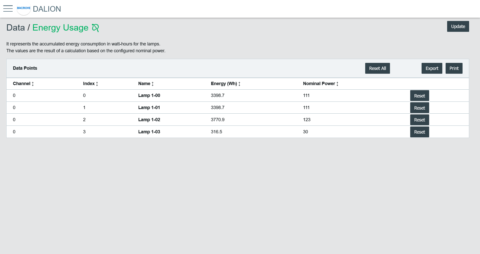
Data Points List
It list the accumulated energy for each configured lamp. Clicking on a collum name allows sorting the table.
Collumns
Channel
The lamp channel number, 1 to 4.
Index
The lamp index number, 0 to 63.
Name
The lamp name.
Energy (Wh)
The accumulated energy.
Nominal Power
The configured nominal power.
Change Time
The last time when the accumulated energy was saved.
Reset Time
The last time when the accumulated energy was reset or directly written.
Buttons
It allows printing the accumulated energy consumption values.
Export
It allows downloading accumulated energy consumption values in a TSV (tab-separated values) file.
Reset All
Reset to zero the accumulated energy consumption for all lamps.
Reset
Reset to zero the accumulated energy consumption for the lamp.
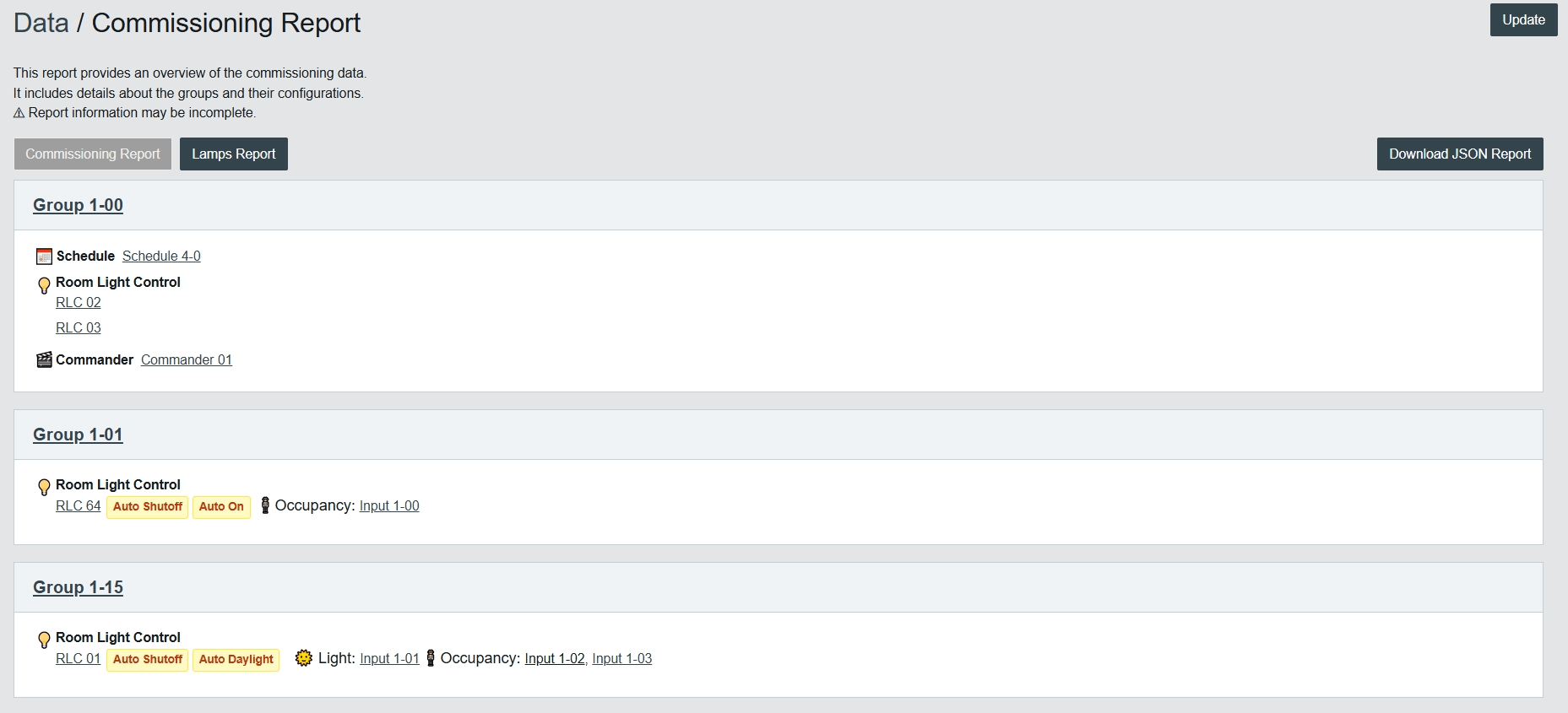
Commissioning Report
Commissioning Report
The Commissioning Report provides an overview of the stored commissioning data.
It includes details about the groups and their associated configurations, such as schedules, Room Light Control, Commanders, and inputs.
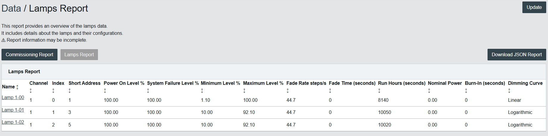
Lamps Report
The Lamps Report provides an overview of the stored lamp data.
It includes details about each lamp and its configuration, such as addressing, levels, fades, dimming curves, and runtime statistics.
Statistics
Many counters are available to help with the diagnostic of network problems for the DALI, BACnet and Ethernet interfaces.
System Log
Displays the system log file that records certain system events.
DALI
Many counters are available to help with the diagnostic of DALI related problems.
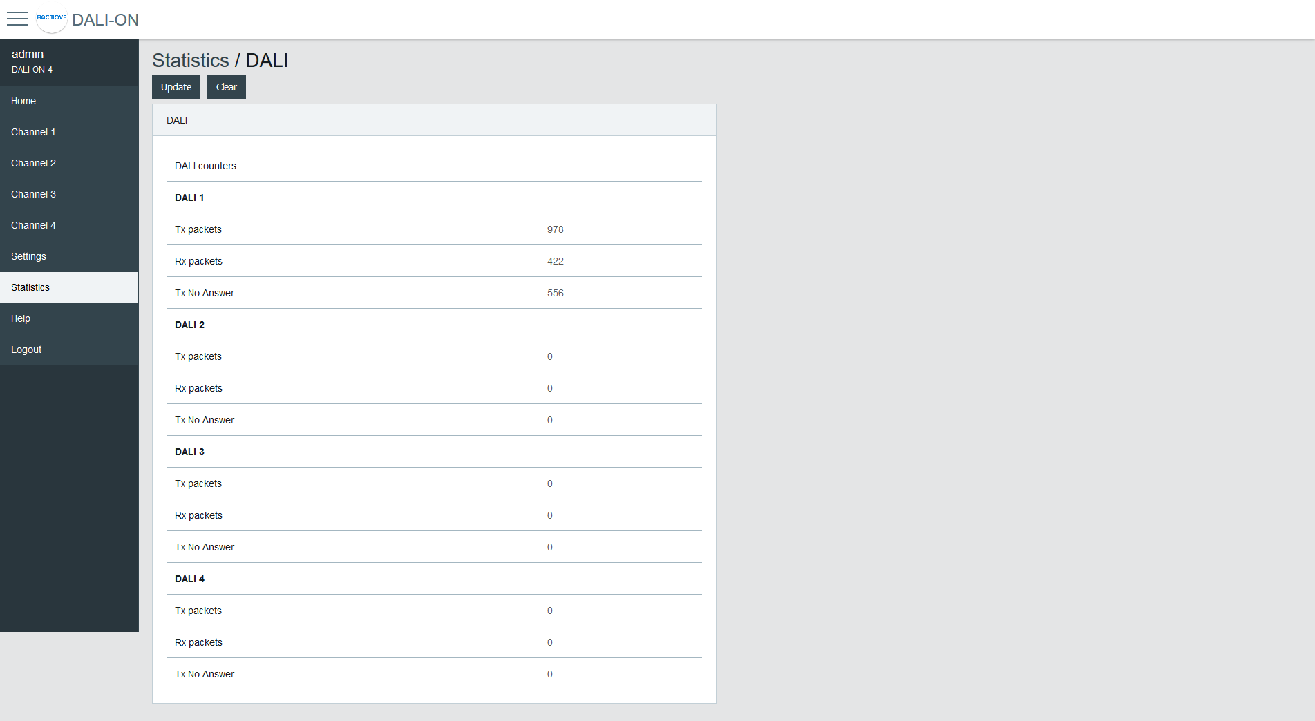
| Name | Description |
|---|---|
| Tx Packets | The number of packets transmitted |
| Rx Packets | The number of packets received |
| Tx No Answer | The number of transmission with a missing answer |
| Rx Bit Timing Violation | The number of bit timing violation detected |
| Tx Collision Avoidance | The number of collisions avoided |
| Tx Collision Detection | The number of collisions detected |
| Tx Timeout Override | The number of canceled transmissions |
DALI protocol analyzer
The analyzer allows network troubleshooting and analysis of the DALI communication protocol. It displays in real time the received and transmitted DALI packets. It is possible to Pause, Clear or Save the data to the computer with the buttons.
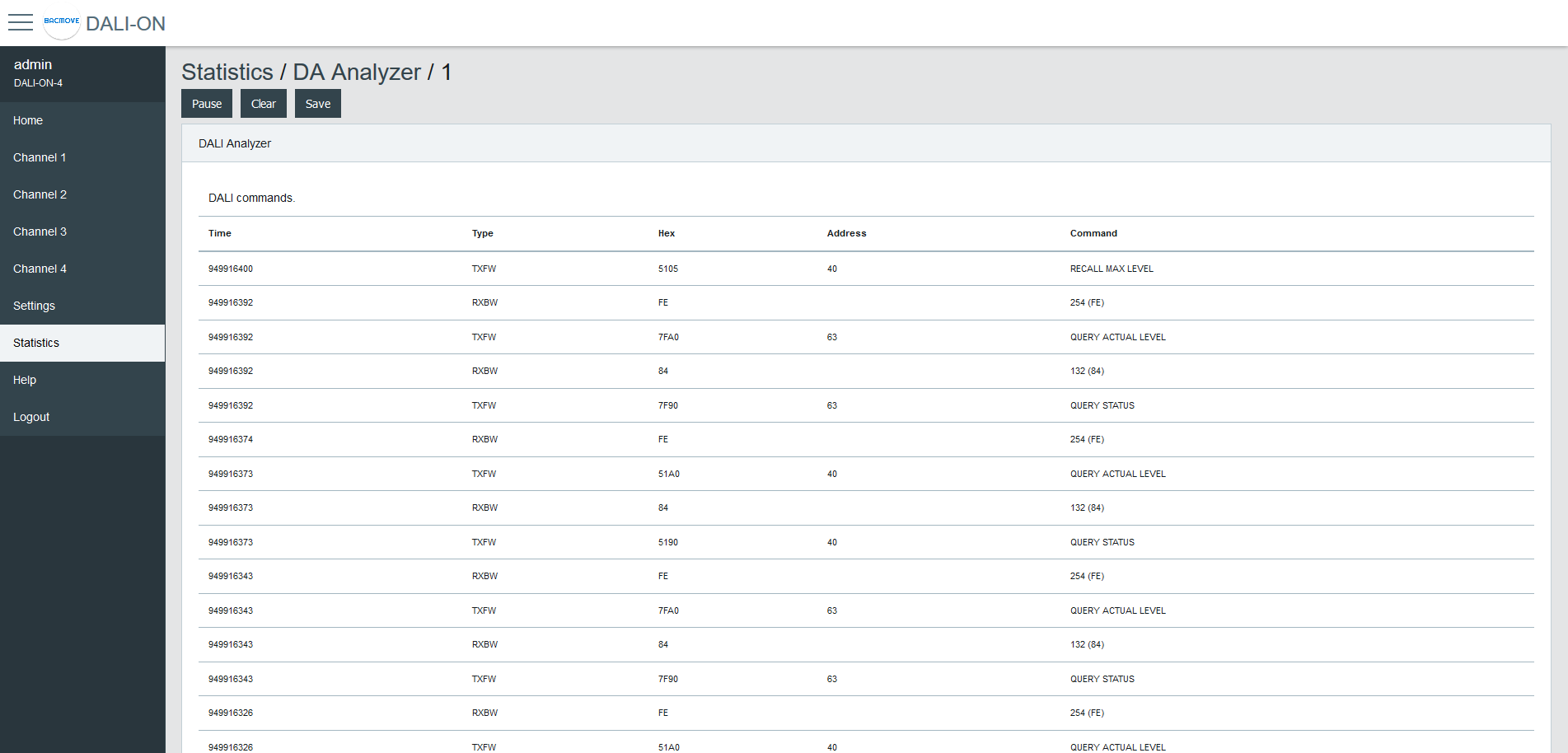
| Name | Description |
|---|---|
| Time | The time the packet was received or transmitted |
| Type | The packet type |
| Hex | Hexadecimal raw data of the packet |
| Address | The packet destination address |
| Command | The command |
Packet Type
| Name | Description |
|---|---|
| TXFW | Transmission of a forward frame |
| TXBW | Transmission of a backward frame |
| RXFW | Reception of a forward frame |
| RXBW | Reception of a backward frame |
BACnet/IP
Many counters are available to help with the diagnostic of BACnet related problems.
| Name | Description |
|---|---|
| Tx Packets | The number of packets transmitted |
| Rx Packets | The number of packets received |
| Dropped Packets | The number of dropped packets |
| BVLC Last Result | The last result of BVLC |
| Invoke ID Unavailable | The number of time a new Invoke ID was unavailable |
| Invoke ID Failed | The number of failed Invoike ID |
| Task Time | Timing of the BACnet task |
| Task Time Error Count | The number of BACnet task timing errors |
| Last Task Time Error | The Last BACnet task timing error |
BACnet Active COV Subscriptions
Displays the list of currently active COV-B subscriptions.
IP
Many counters are available to help with the diagnostic of problems with the IP (Internet Protocol) communication stack.
TCP
Many counters are available to help with the diagnostic of problems with the TCP (Transmission Control Protocol) communication stack.
UDP
Many counters are available to help with the diagnostic of problems with the UDP (User Datagram Protocol) communication stack.
ARP
Many counters are available to help with the diagnostic of problems with the ARP (Address Resolution Protocol) communication stack.
ICMP
Many counters are available to help with the diagnostic of problems with the ICMP (Internet Control Message Protocol) communication stack.
ARP Table
This page displays the current ARP (Address Resolution Protocol) cache where IP addresses are associated with Ethernet MAC addresses.
IP Memory
This page displays the current memory usage of the IP stack.
Ethernet
This page displays the current value of some Ethernet registers.
General
This page displays general counters and memory usage.
System Tasks
This page displays the task usage.
File System
This page displays the file system usage.